by JRinTawa
- Topic started 25th September, last instalment (for now) added 1st October.
Our railway, the H&MGR, has been in operation for some 9½ years, the just under 50m of single line mainline in a folded figure of 8 has given great service but with the introduction of live steam the need for a proper steaming bay was becoming a more and more desirable addition as each new steamie was put into service. Of course these things have a habit of growing and not only did we gain a steaming bay but we gained a reverse loop, Y junction and an increase in total mainline to approximately 75m in length.
There were some other gains in doing the extension as an upgrading of two areas of the garden, that had passed their best if they had ever had a best, was achieved and so not only has the railway gained a new lease of life, but so has the garden. My dear wife now has a sun deck to drink coffee on while chatting to the birds in the adjacent aviary - a win win situation.
In the process I have taken the opportunity to trial a few different methods to create the track roadbed from the solely track laid on grade in loose sand ballast on a compacted basecourse subbase. This Topic I hope will be of interest as I walk through the project, and illustrate some of the construct carried out.
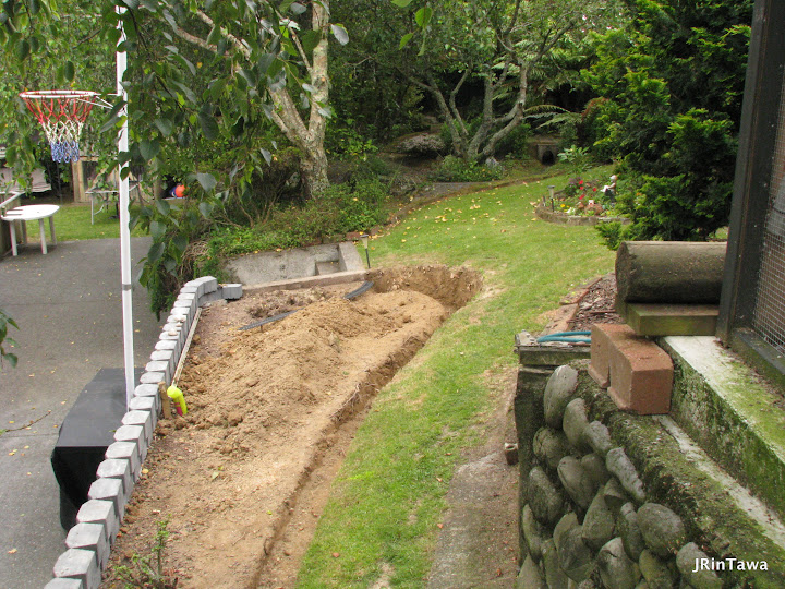
It all started with felling a tree.
While I like my trees, a Silver Birch adjacent our kitchen really had got to big and needed to go to lighten things up. I had pondered and played with various ideas to extend the railway over the last few years but none really fell into place. With the Silver Birch down a workable possibility just started to fall into place.
The stump took a bit of work to get out, and there certainly wasn't much garden left!
To level the area off a little bit of extra retaining was required, this improved the grass path to the aviary too, another win!
Another of those jobs I had put off for years was pouring some new steps to replace some poorly formed and steep steps. A further win :-)
Time to try out some track configuration.
Previously I have used Aristocraft wide radius turnouts (points/switches) but with the demise of Aristocraft I opted to try Piko turnouts on the extension. For the Y I opted for their R7 (1560mm / 10ft diameter ) turnouts.
It took a bit of thinking and carefully comparing of radii to find just the right spot to decide where to cut the new turnouts into the old main line.
I tried the R7 turnouts in the steaming back area but in the end opted for the slightly tighter R5 (1240mm / 8ft diameter ) ones. R7's in the photo.
Behind the wall I have backfilled with well tamped (likely compacted) 20mm domestic basecourse as a track subbase. Looks Like I've gained a pond in the hole where the tree stump was. Yet another win!
The turnout at the southend of Kakariki yard was the first one cut in. Splitjaw rail clamps used, as I always do when laying turnouts, as it makes removal for future maintenance much easier.
Better do a test of the work so far.
Laying the Y Junction. (added 28th Sept)
First stage was to permanently fix plastic composite decking that form the track base from the turnout cut in just south of Kakariki station to just before the where the track runs across the top of the new steps. Rather than use normal timber decking, which in NZ is H3 treated and should really not be used within 150mm of the ground and also should have good air circulation to maintain it's integrity. Sure timber decking probably would last long enough to meet my needs in this case but I wanted to try out the plastic decking for this type of use with a possible eye to future extensions or layouts.
In addition to being close to the ground, and I hope soon to be lost in amongst plant growth, roots from the adjacent Silver Birch needed to be overcome. To achieve this I drove some 15mm diameter aluminium tubes, 450mm long at some 300-400mm centres along each side of the decking. (The tubes have since been painted black.) Stainless steel screws fixed through the tubes into the side of the decking, the decking pre-drill for the screws. Some tube locations needed a couple of tries to miss tree roots.
What do I think about the plastic decking? Horrible stuff to work with, inclined to split if you don't pre-drill for screws in the sides (good idea to pre-drill in all locations just in case), and will sag in hot weather or direct sun if not well supported, however I do think it will work okay despite that.
The track is screwed to the decking after double checking it was aligned and levelled properly. In time I will ballast with either Rowlands mix or sand and cement.
Now when laying track only a mad man would lay a turnout in the top step of concrete steps. Yep, I've laid a turnout in the top step of concrete steps! Firstly pour the step with an appropriate channel along the track alignment...
...then set the track in with a weak mortar mix. I laid some strips of timber, about 8mm x 5mm to form the flange ways as the mortar was placed. Great care was taken to keep mortar out of the turnout blades, aided by some tape I stuck to the underside of the moving parts of the turnout (it was a dog to get the tape out later!). Oh yes and great care was taken to make sure the turnout was level in all directions.
To protect the track, in particular the turnout blades, when the railway is not in use rubber mats are placed over the track.
So far this junction has worked except for silt which washes under the tie bar. What I should have done is to install a pipe/drain under the area of the tie bar so rain can drain away taking the silt with it and when I flush the turnout with the hose the mucky water can run away and not towards the pond! I have a cunning plan to retro fit a drain to resolve this. However train do run over the track and turnout well, but the point blades do not flick across as reliably as the other new turnouts installed.
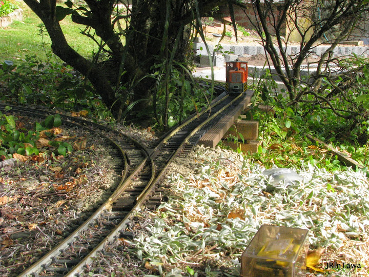
With the step junction turnout installed the other leg of the Y from the step junction to a turnout cut in to the old main line near the trestle bridge, now know as Junction Bridge, was laid.
This section of track laid on grade with a compacted basecourse subgrade with sharp sand ballast with a dressing of crusted limestone where a dirt road will be detailed at sometime in the future.
There was a bit of work to cut back the rock face that formed the existing abutment to Junction Bridge and then realign the rocks, choosing the most weathered and mossy faces and dressing up other areas with hypa-tufa mix (sand, cement and peat mix plaster). On the face just past the Dubs A I pressed moss scavenged from elsewhere in the garden into the wet hype-tufa. Some moss later falls out but enough takes to speed up lovely moss growth.
The cattle stop in the photo below was previously positioned about where the turnout frog now is. When this area is finally detailed where the dirt road crosses and runs along the track wooden planking will be installed in a similar way to timber running boards have been used on our existing level crossings. I can see the idea in my imaginations!
So now we have a fully functioning Y junction and some nice new steps!The Steam Up Bay.
With the area already backfilled and roughly levelled with compacted 20mm domestic basecourse, and the garden area topsoiled, when the next back of turnouts arrived, Piko R5 ones (1240mm / 8ft diameter ), it was a pretty quick job to lay the track "on grade". To final bring the subbase to level I first lay some of the sharp sand used for ballast, then lay the track, tamp it into the sand then dress with more sharp sand ballast, finally watering to bed in.
Just add some planting and bark mulch and it's looking more like a finished job. At this stage just what form the bridge over the pond will take is uncertain. As for the pond, well it's more like a puddle than a pond, but we will see how that develops too.
Some extensive testing now took place. This was going to be the extent of it, I was only trying to gain a steaming bay!The Reverse Curve, an unexpected idea.
It was the cats idea! There were a couple of things to overcome first, thankfully approval from my wife wasn't one of them, she was right behind the idea form the start. Not the least being fitting between and around a couple of trees, a steep slope and a hulking big rock that in the photo below can be seen at then then present end of the steaming bay extension!
It all fell into place when I come up with a plan to build a deck for the partaking of coffee while enjoying the afternoon sun alongside the girls aviary. The poles in the photo are for the deck, initially I thought I could suspend the track from under the deck, but in the end separate 100x75mm fence posts set in concrete piles was a simpler, and better, choice.
Work now proceeded to form a trellis lathe spline type roadbed. I did contemplate building this in the carport using a template to get the theoretical curve required, but as the following photos will show I built it in-situ. A tricky job on the slope and around the trees but easier to get the curve right I felt. It was at this stage while testing out how the well the trellis lathe (40x10mm) would curve and at what spacing would suit the 45mm gauge track that I discovered that the 75mm width of the posts was really a bit fat for the sleeper width of the track.In the photo below you'll note that I laid a concrete slab at the top of the slope, to provide a solid permanent track base under the deck and to support the toe of a small existing retaining wall that had doubtful foundations. Bedding in some rocks helped with this aspect as well.
Having worked out I need to trim a bit from each side of the posts to get a post width of 66mm. The lathes on each side of the posts could then be fixed, screwed and glue with two pot carpentry exterior glue to the posts carefully measuring from a centre peg I had installed to ensure I kept a constant radius. The centre peg had been installed earlier as part of the working out if the reverse curve could be built. It was used also for setting out the 100x75mm posts to ensure they were in the right place and orientated correctly when installed. Of course the lathes where also checked for level laterally and well as along the track line as they were installed. The centre lathe went in next then the outer two with spacers at quarter points between the posts.
The two photos below, looking down on two posts, one on the curve at left and a post coming off the curve at right. As you can see I cut a slot through the post centre line so the centre lathe could be run straight through. Having the lathes installed either side of the posts gave a level surface to run the circular saw along as the 10-12mm wide slot was cut. On the track I was using (NZ supplier Quayle Rail) the sleepers are 88mm long so to be safe I set the lathes either side of the posts to be at about 86mm overall, hence why the posts were trimmed to 66mm width.
The theoretically spacing used was: -
lathe / spacer / lathe / post or spacer / lathe / post or spacer / lathe / spacer / lathe
10mm / 32mm / 10mm / 28mm / 10mm / 28mm / 10mm / 32mm / 10mm giving and overall with of 170mm.
Of course there was a few millimetres variance as I went along but it worked out okay. At the posts all joints were glued and screwed, for the quarter and half span locations the spacers were glued and nailed. Sounds strong doesn't it? And it is, I tried standing on it as a test when completed and it past!
There was a bit of a fudge where the trellis lathe roadbed mets the retaining wall, so don't look to hard. Messy but it worked. Not helped by having to negotiate yet more tree roots, so more pipe piles driven rather than digging in a timber post.
The short straight section to the left of the tree was supported initially just on brackets fixed into the existing wooden retaining wall (covered with vegetation in the photo). However the brackets weren't strong enough on their own, the roadbed drooped. So two pipe piles driven to support the edge away from the wall. I'm becoming quite a fan of these pipe piles where the roadbed is not to high off the ground.
Phew. Time to lay the track, curved in-situ with a borrowed dual rail bender. These dual rail benders really are the way to go, nice smooth curves, perfect.
Once bent the track was screwed to the centre lathe.
And time to test. Track laying must have been okay, nothing derailed, but the drop is a bit nerve racking!
Dressing up the Reverse Loop
The edgeless roadbed of course couldn't stay that way, the drop is just to big to risk. Scrap bits of the trellis lathe were cut to make 12mm x 10mm x 140mm long posts, drilled for 2.5mm soft PVC coated wire, threaded onto the wire then glued and screwed to the outside lathes at 150mm centres. The wire is some Gabion basket lacing wire I'd been saving for years, it is a soft galvanised wire and the dark green colour suits the location I feel. On reflection I think I got the posts a little high, but the intention was more for security than looks in this case.
The section of track which will be under the deck, as mentioned about, is on a concrete slab. Once it had passed the running test it was fixed in place with a coarse sand mortar, this I hope will allow any accumulated debris to be easily brushed clear. It's working so far!
Planting and mulch and we're ready to build the deck. Having seen on video and in photos of Neil Ramsay's railway how well Lonicera Nitida can be shaped to provide a convincing landscape under elevated track I opted to use the same, choosing a mix of green and variegated type. Just how well they grow under the deck shadow line and with the tree cover is to be seen. Lonicera grows quickly but in this semi-shade location I expect the growth will be slower than usual.
So that is about it. I won't bore you with the same blow by blow detail of building the deck but suffice to say it is a great spot for watching the railway while enjoying a coffee. You can't see all the railway from the deck, trains disappearing into the distance just like a full size railway, not that I get to sit around on the deck much, that it my wife's job.
One last photo :-)
1st October and that is the topic done for now. I'll do an update in a few months time to report on just how the various methods are holding up.