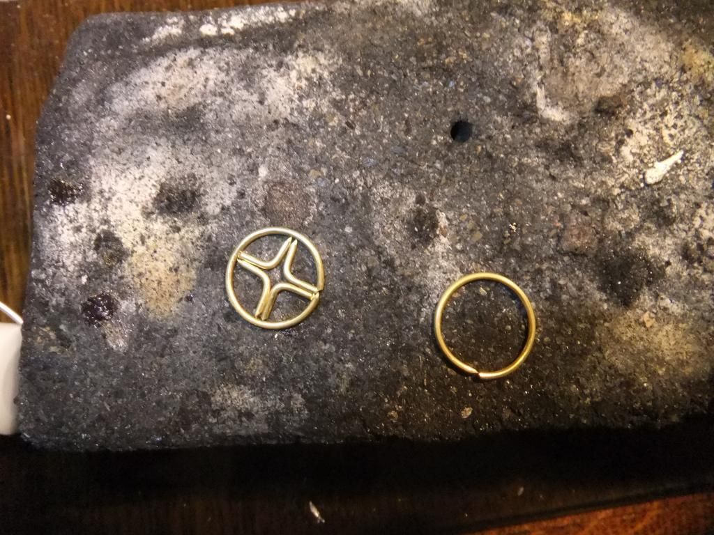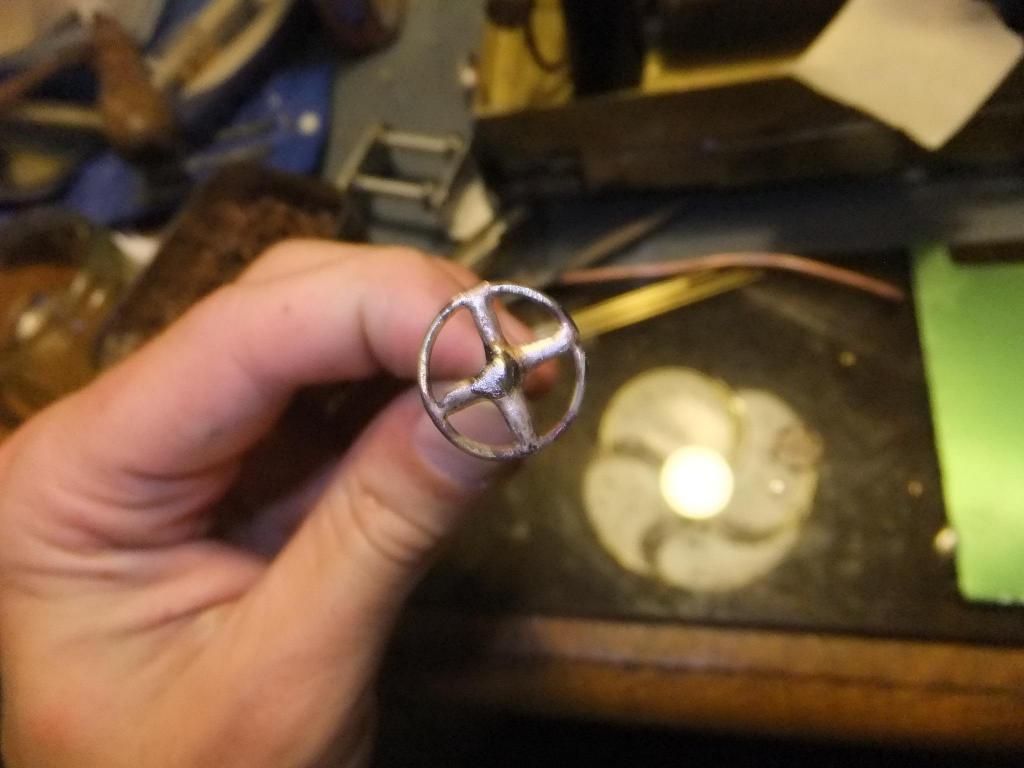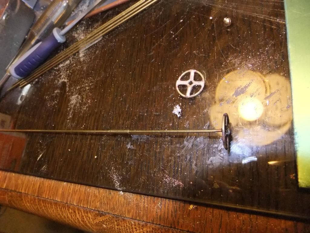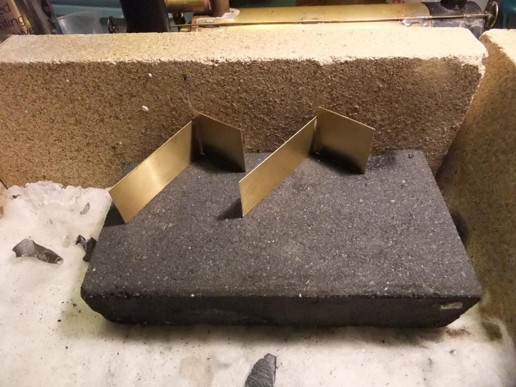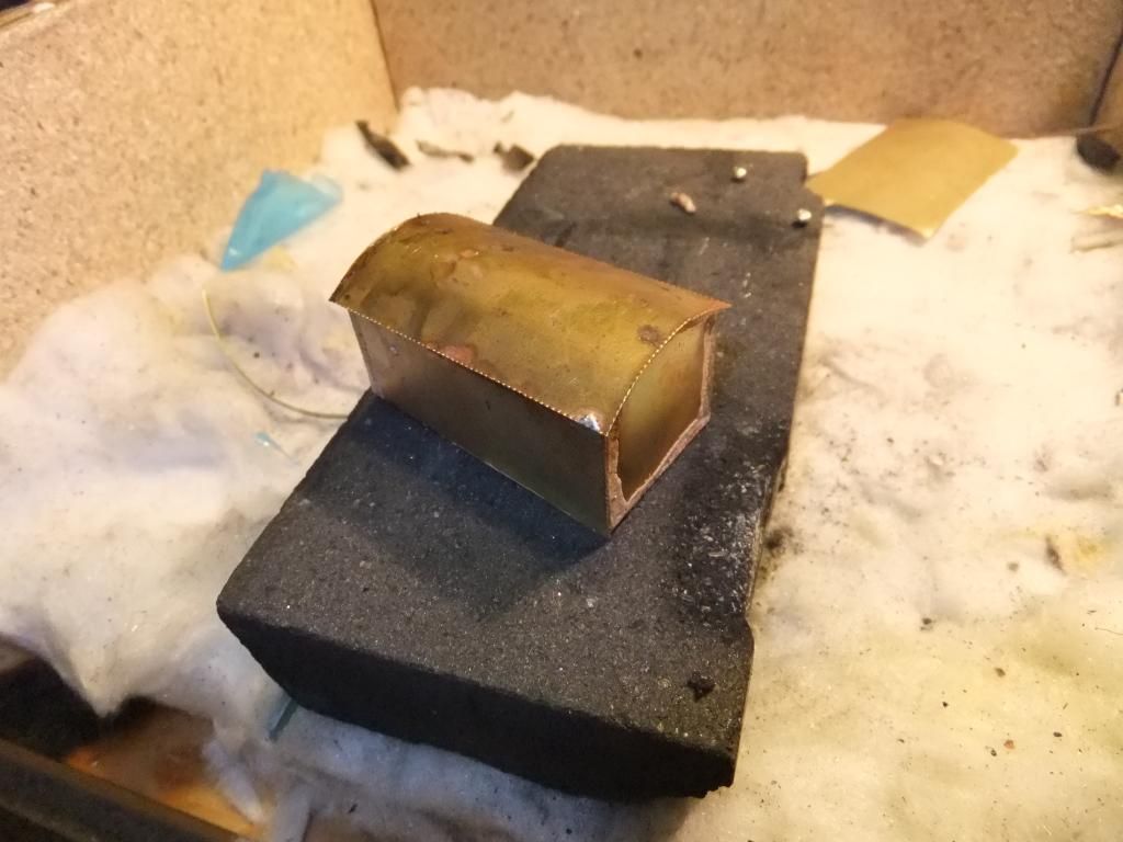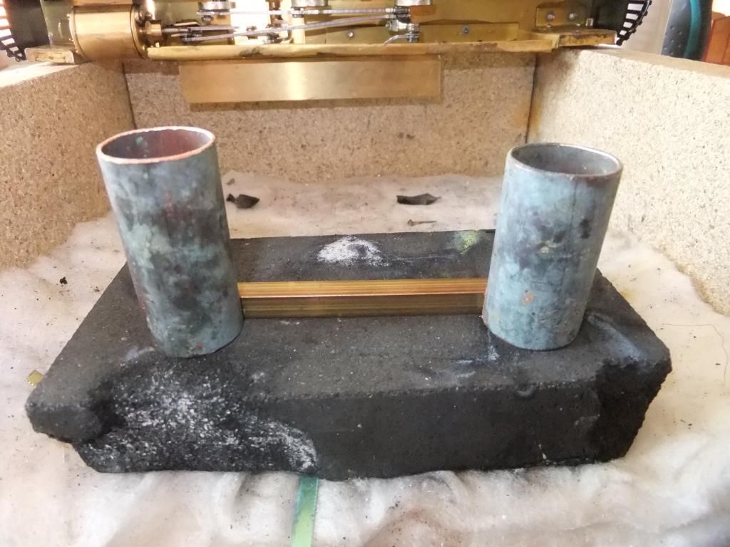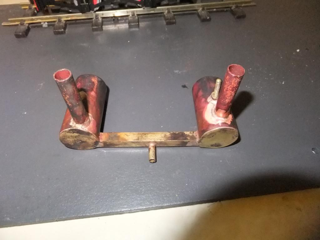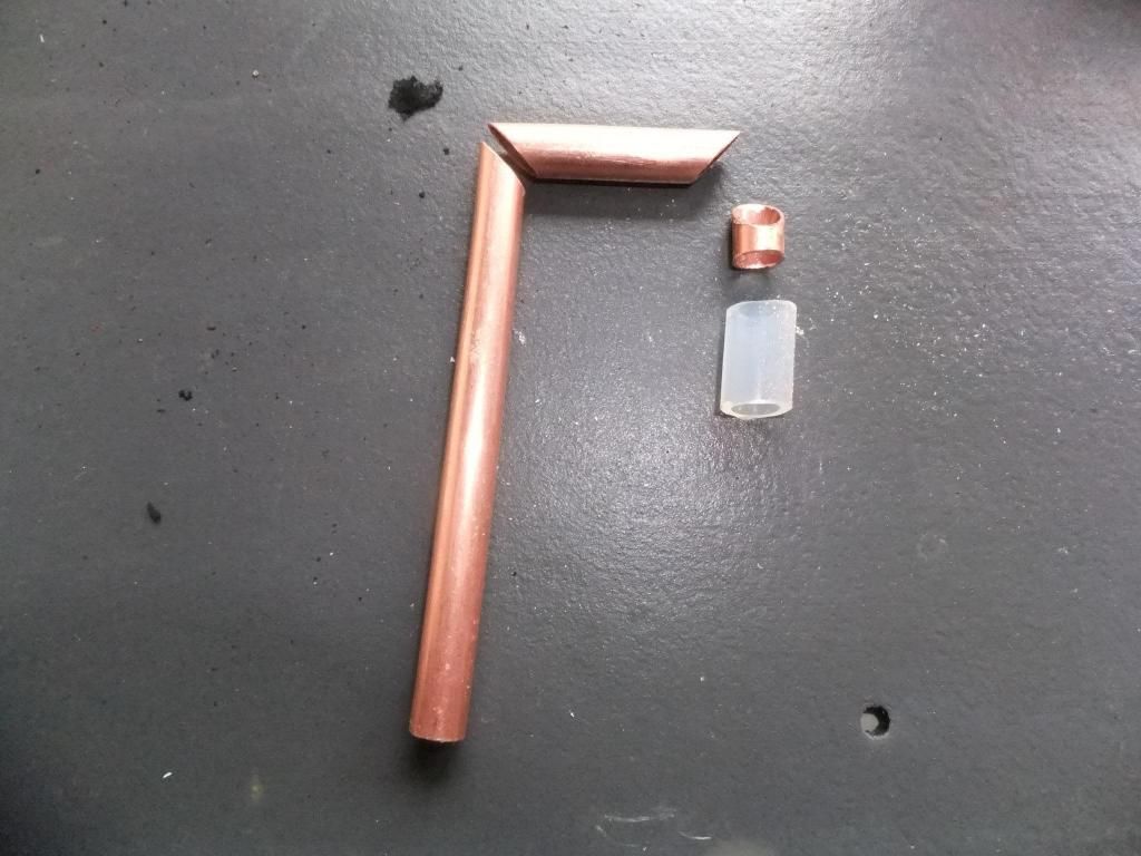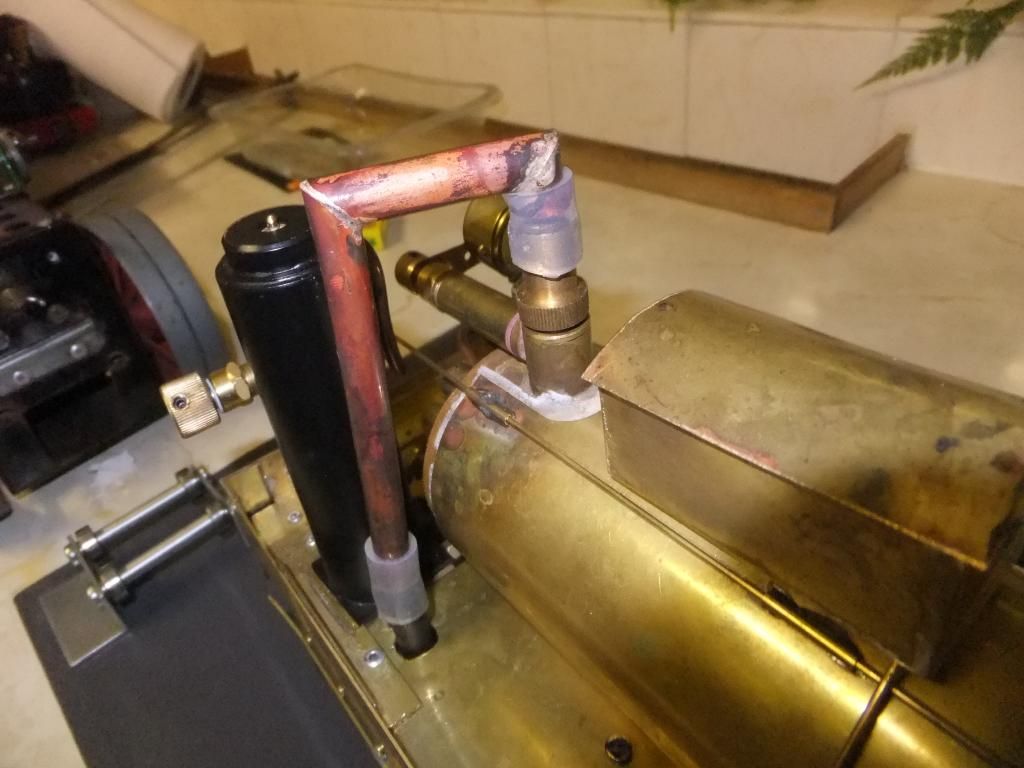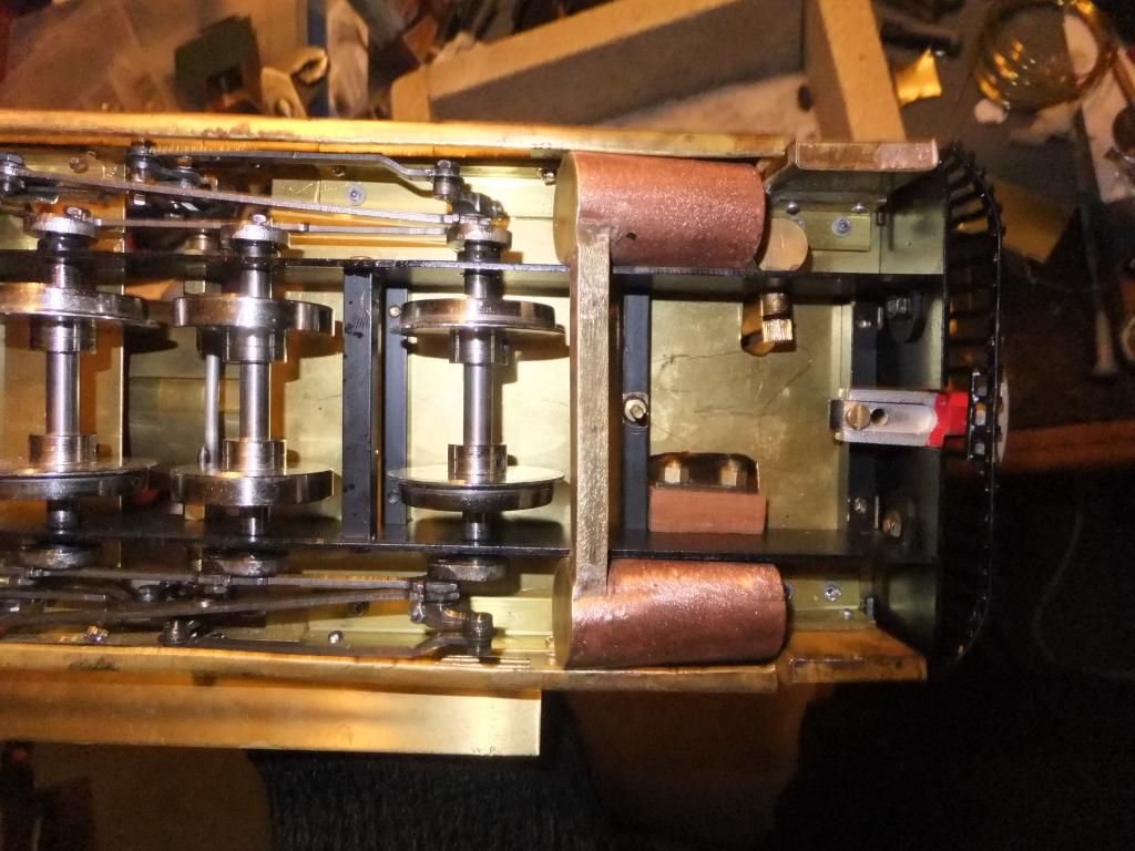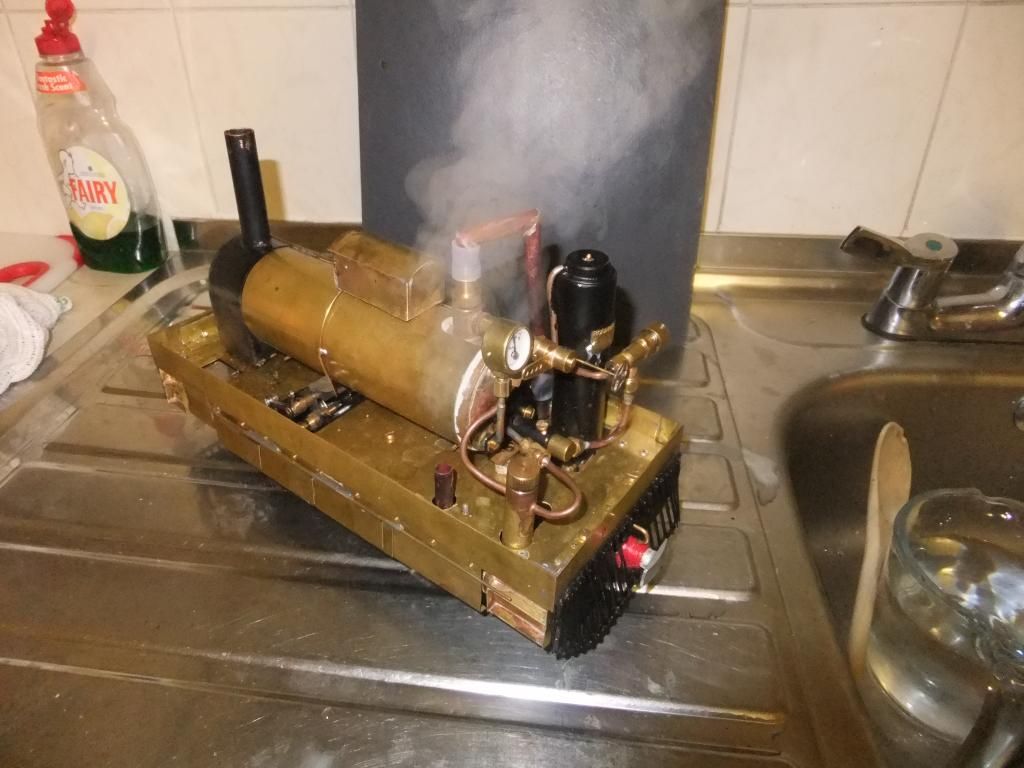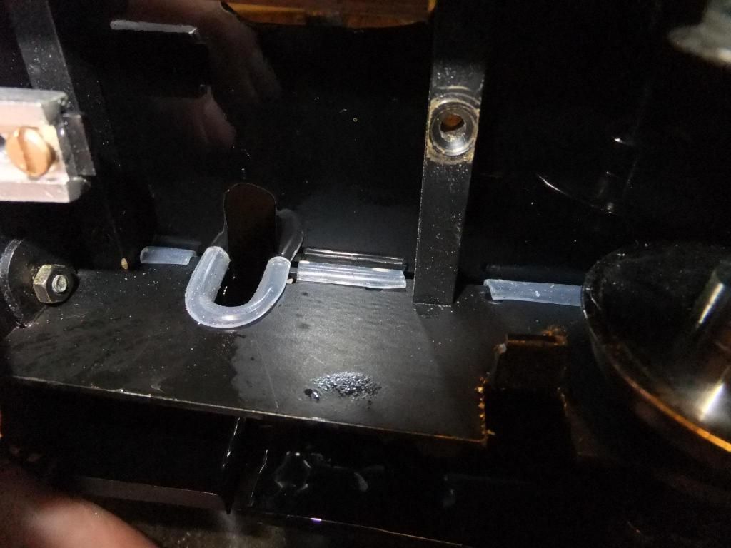
by Mark 'Ace' Pengelley The idea The basis of this loco has a deep rooted source. It all began in my childhood years of watching my favourite TV series 'Thomas the Tank Engine'. Toby was one of my favourite characters and I loved his unusual lines, temperament and usefulness along with the unusual Henrietta and other assorted rolling stock. Fast forward about 25 years and that brings me up to now. It was all decided as a quick brain storm session with my Dad one evening that we should build a tram like Toby. A few google searches later and that brought me to finding the exact basis and models that Toby was prototyped on. I read dozens of publications on the various trams that Toby was prototyped on and the line on which the Y6 (0-4-0) and the J70 (0-6-0) trams operated, the Wisbech & Upwell tramway. Trade was mostly seasonal with fruit, coal and passenger duties also incorporated. So here is a typical J70 tram. Image from the LNER info encyclopaedia website ( Click here to see the J70 at LNER.info ) Below is a couple of images of a J70 tram. 68222 is standing in latter BR days and was believed to be the last one standing. 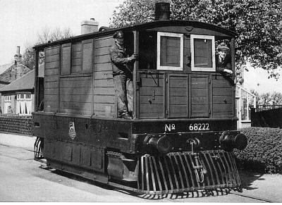 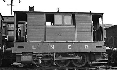 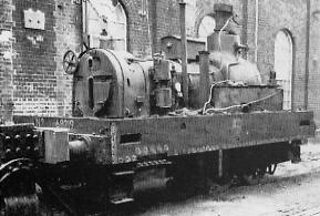 Project objectives In the beginning the aim was clear. It was originally decided to keep the design simple, relatively low budget but above all to look right on a typical narrow gauge line (not so easy for a standard gauge locomotive) so to kick off I originally was thinking about basing the chassis and running gear on a Mamod/Mss style of setup. I had plenty of parts lingering around the place to mock up a small rolling chassis and do a couple of cardboard bits and pieces. A spare Roundhouse Lady Anne boiler was donated to the project as it was surplus to requirements due incorrect replacement by total mistake about 10 years prior for another locomotive. Things have a way of just working out! 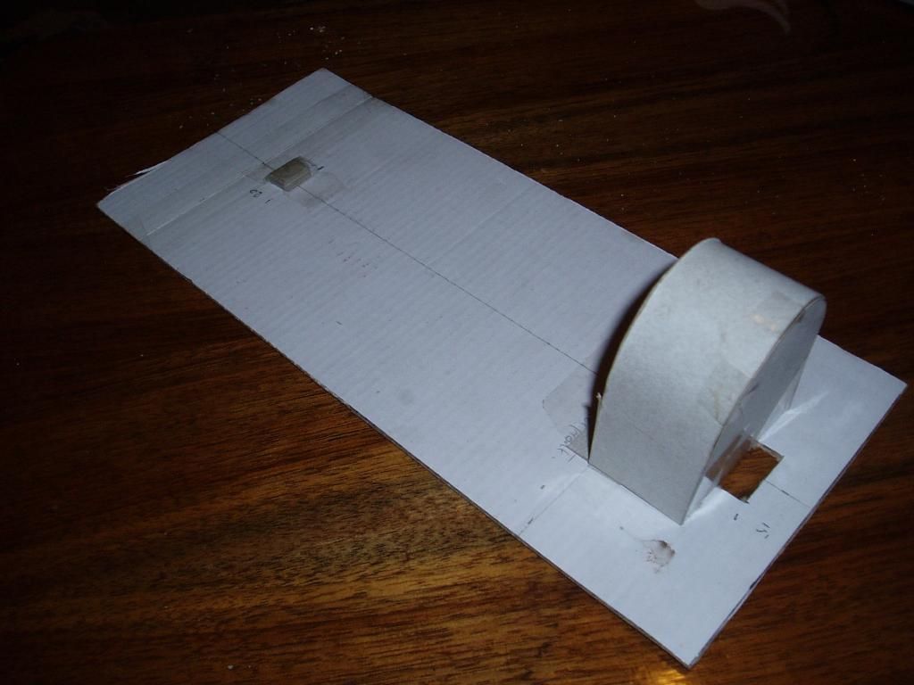 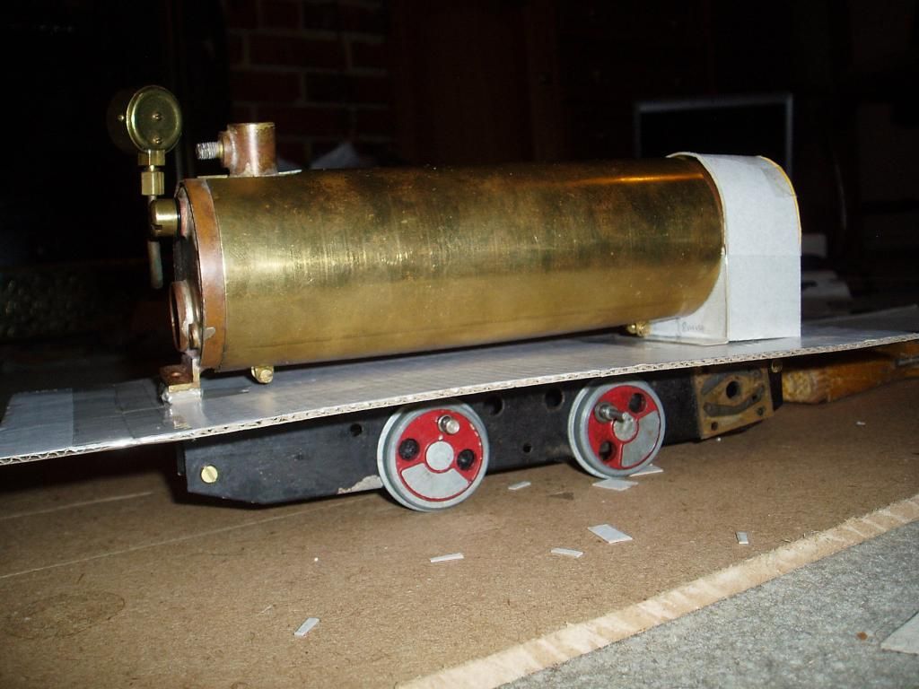 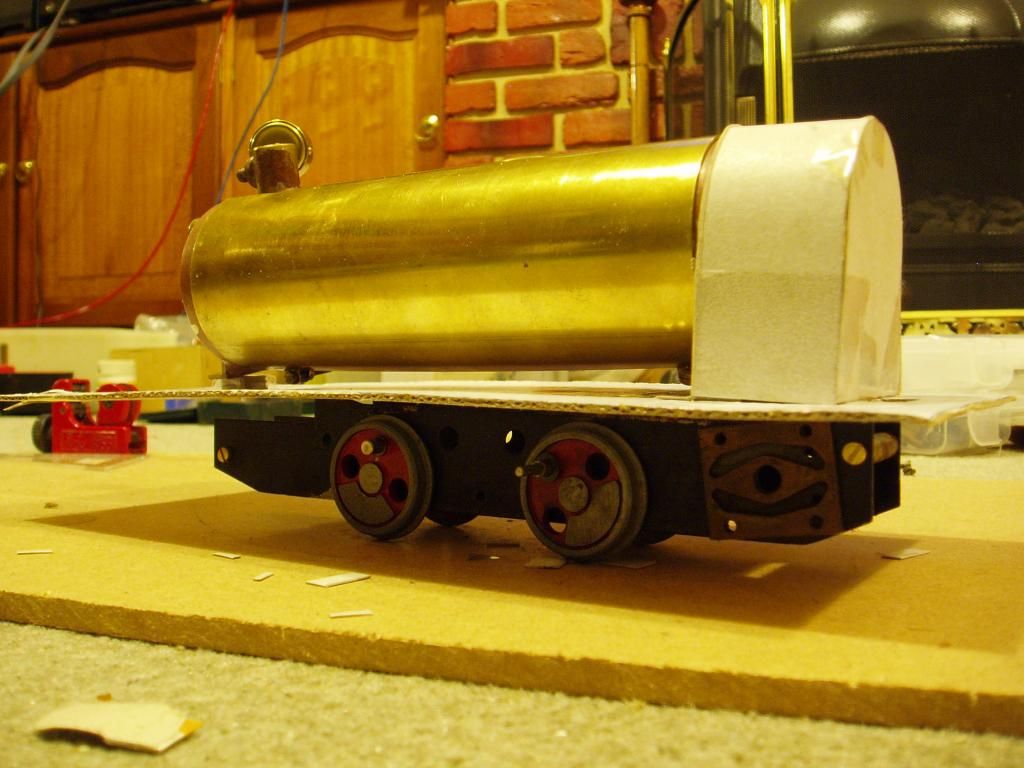 So with a rough plan in mind and fire in my belly about the whole thing I got started, that was until I realised how ridiculously unstable the above set-up actually was. The idea was temporarily put on-hold until I had enough time to think about it. A few days later I was playing with my Roundhouse Billy (I still own) and running my Mamod SL1 for a bit of fun. The difference in running capabilities was glaringly obvious and suddenly like a ton of bricks, it hit me. The Roundhouse model had infinitely more levels of refinement than the Mamod and the pulling power was ridiculous for the scale of the Roundhouse Billy. Then I remembered, Roundhouse Engineering sell kits! Less than an hour later I was on the Roundhouse website and had ordered a Lady Anne chassis kit. There goes the 'low budget' idea! So whilst I waiting for the chassis kit to arrive, I decided to crack on with the smoke box. I don't know why? I just had a bee in my bonnet about getting it made, so I did. Some steel was cut, formed and silver soldered together and was a perfect fit for the end of the boiler. I used the height of Billy's rear boiler spacer to help with the overall height of the smokebox because I knew that the floor of the tram was going to be flat. 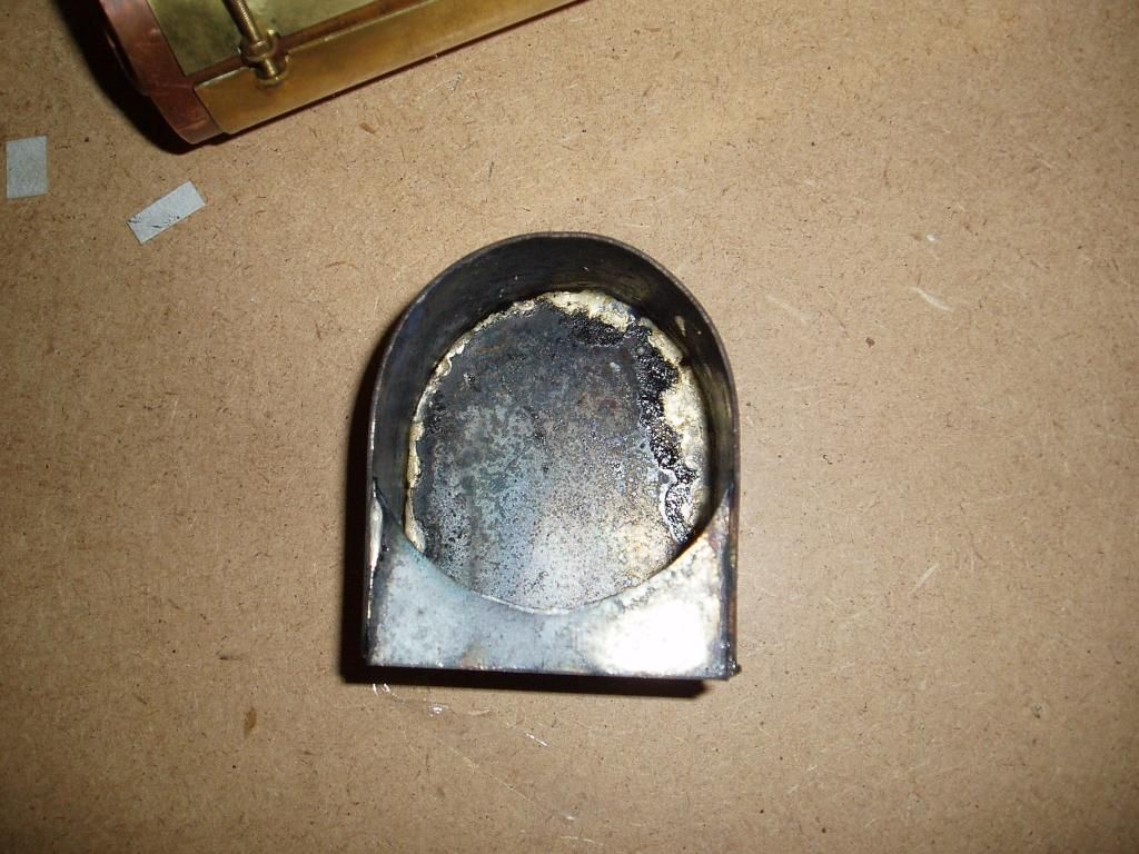 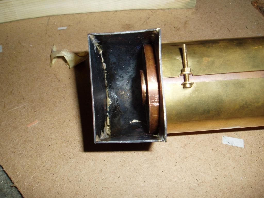 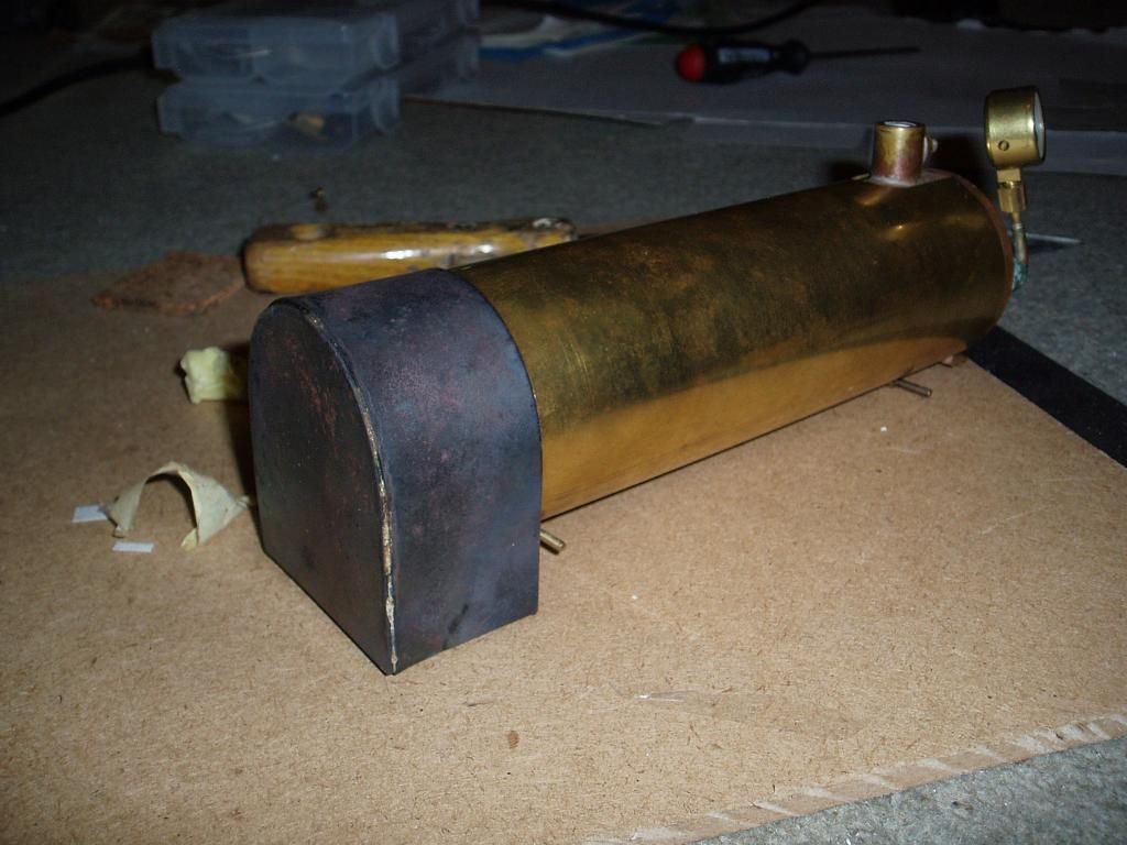 Next up for the smoke box was a chimney, something nice and easy and to hand was used. A short length of 15 mm copper pipe. 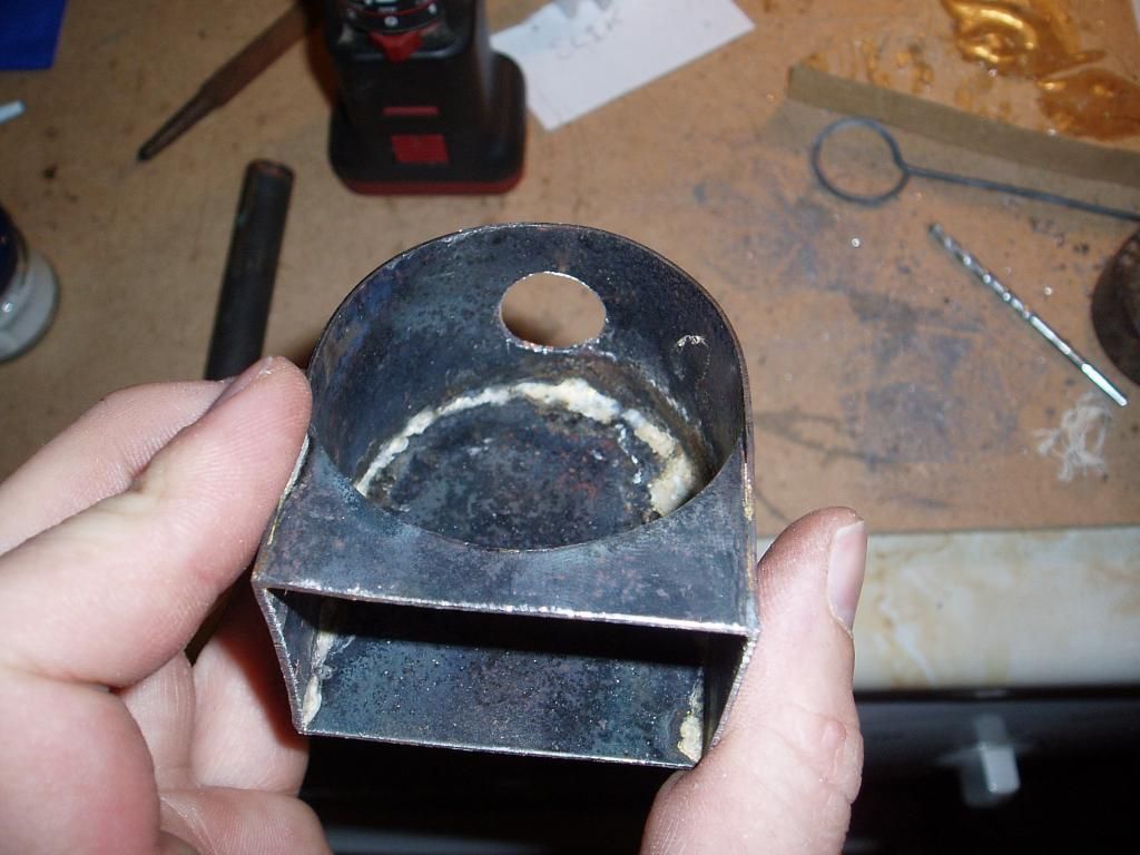 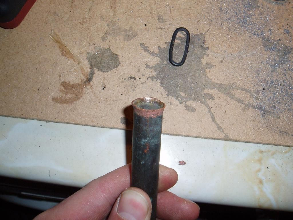 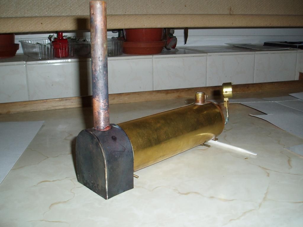 Parcel from Roundhouse, not what you'd expect. I'll move quickly off topic for a moment. The parcel arrived from Roundhouse, excellent! A little large, maybe a lot of packing? Not likely, it was a Roundhouse Jack. One of the limited run in 2010, number 017 of 100. Was I a lucky chap or what? 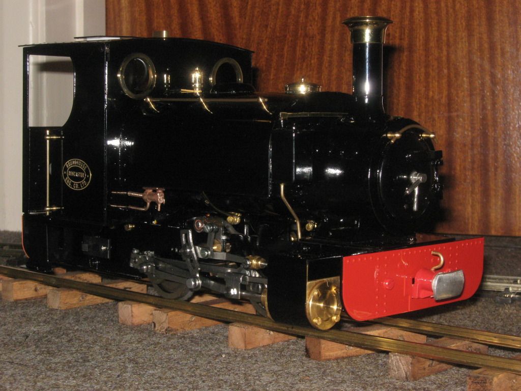 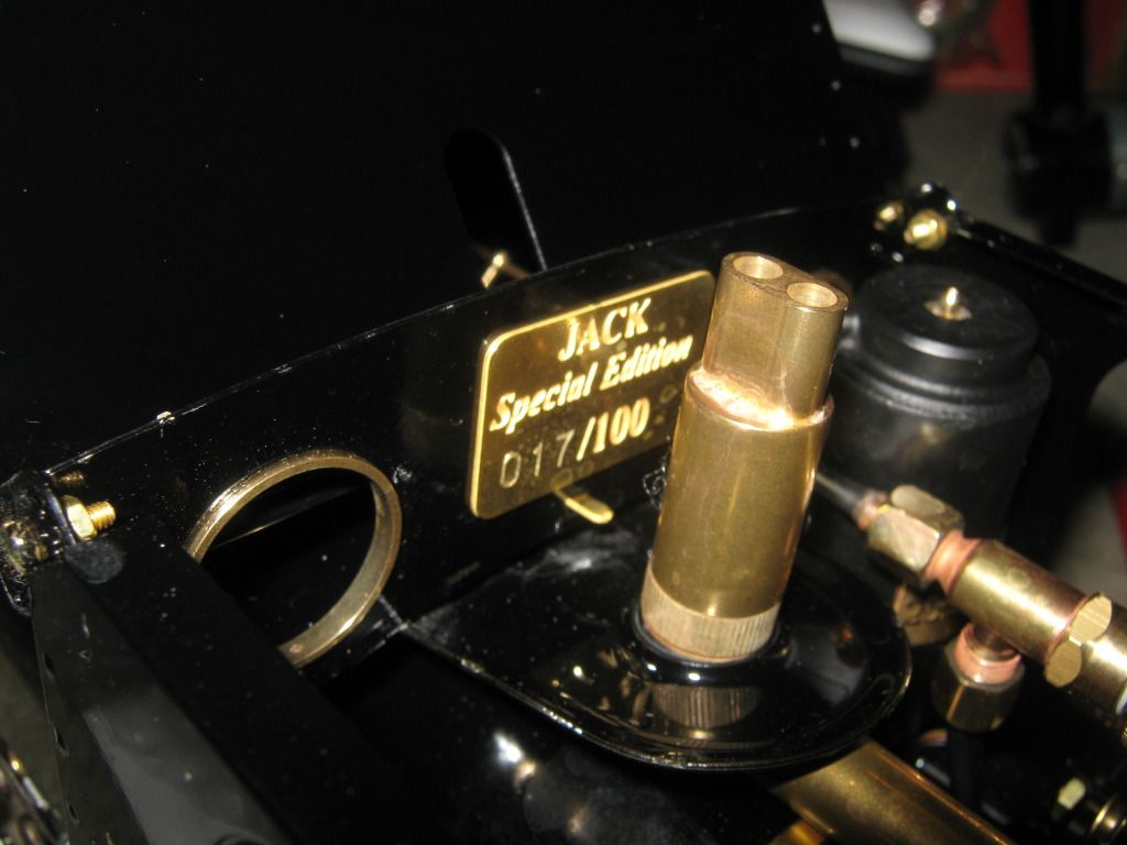  A quick phone call to Roundhouse and I agreed to send Jack to the correct owner and meanwhile my chassis kit came over to me. I would love to know who owns Jack 017 and bit about his travels so far. Parcel from Roundhouse, take two. So now I have my new chassis kit and here are the parts. A quick inventory check showed I had all the correct parts plus a couple of extras in case of loss or breakage, how thoughtful! I started on with the refinishing and continued with the assembly. Anyone who has ever built one of these kits will know they go together very easily with good instructions to follow. Most of it is really straight forward, almost anyone could build it. 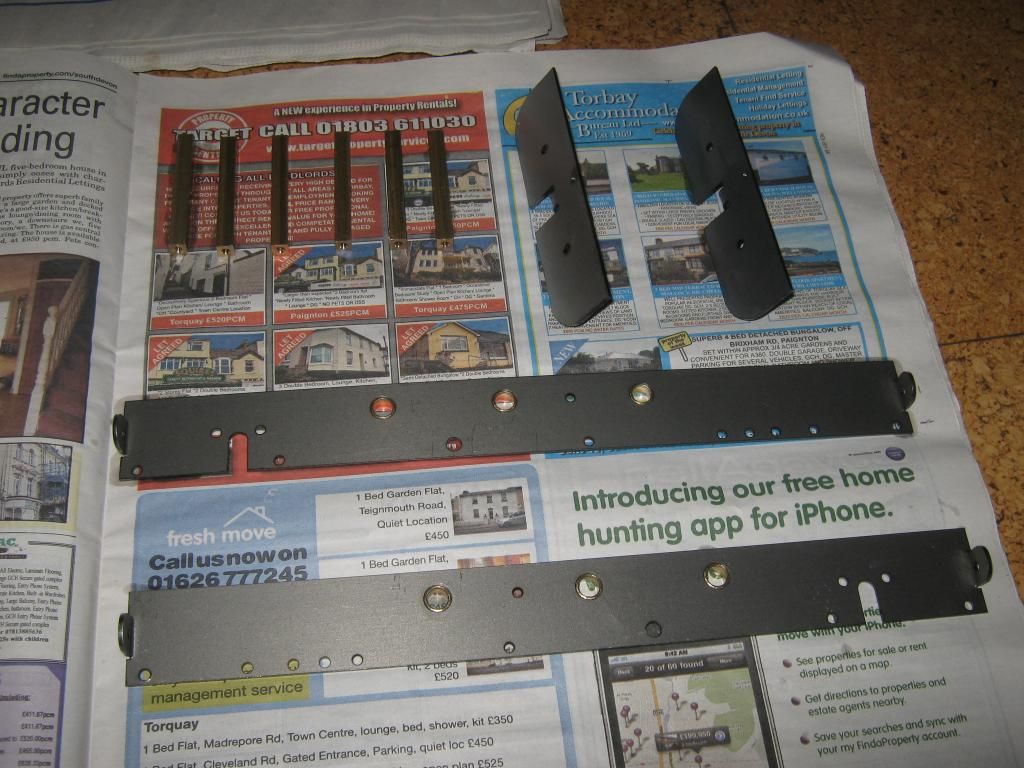 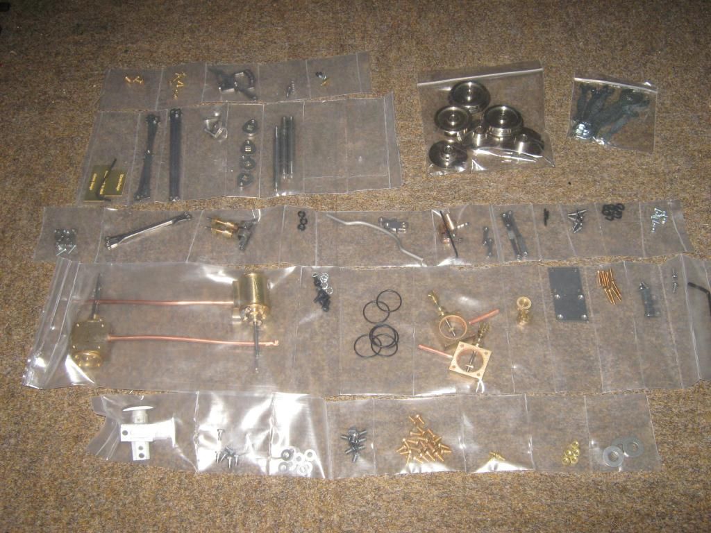  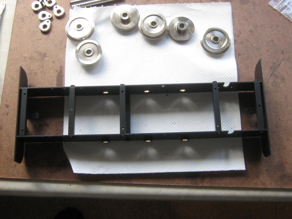 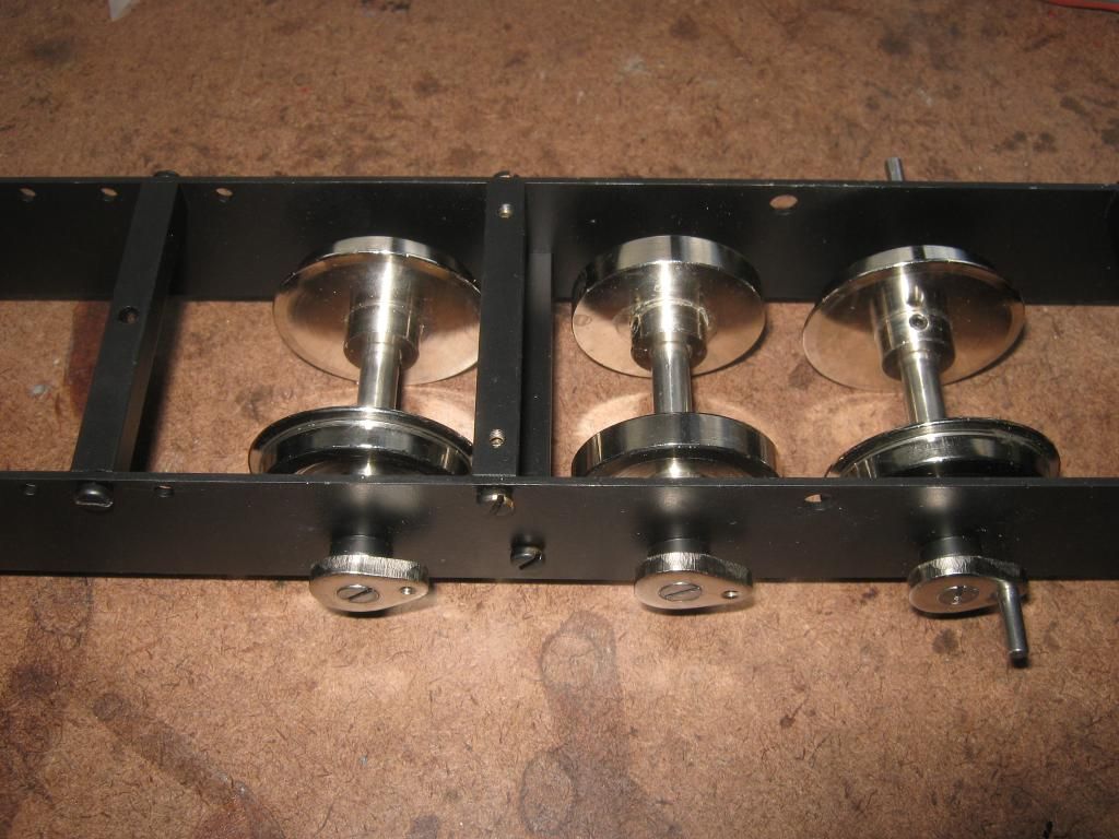 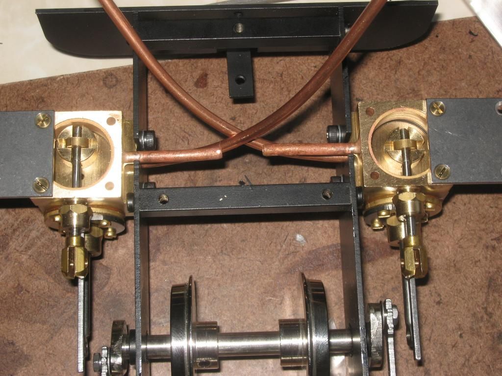 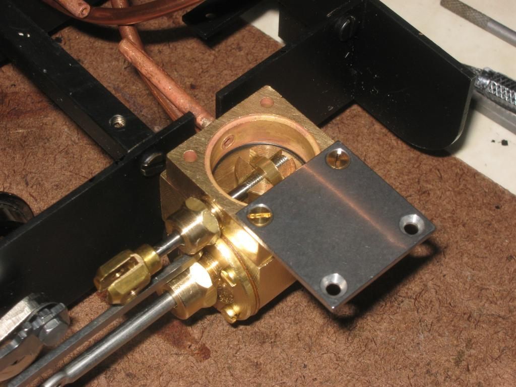 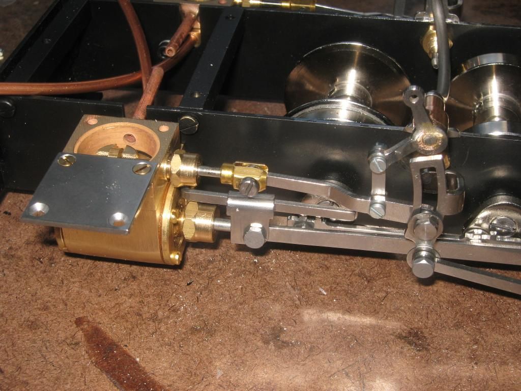 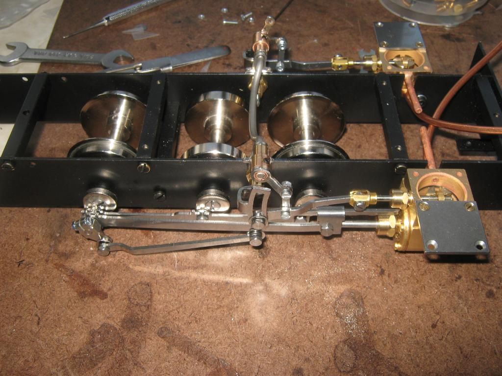 Once the chassis was completed I used some light oil on the internal moving parts and tried it on compressed air. Please excuse the poor video, it was among one of the first videos I had ever made, please also bear in mind this was the first time I have ever built and ran a chassis and be left to my own devices to set one up. Looking back on it now I can clearly see things that are not right. The body With the best part of the chassis put together with the cylinders and valve gear roughly assembled, the base was ready for the body assembly to begin. The idea behind the body was simple, I wanted a large removable section for easy maintenance, filling up and tweaking. I didn't know what I was going to need to do so I wanted to make the tram as easy as possible to take apart and put back together. This is where scales and measurements went completely out of the window, this locomotive was going to be built on 'eyeball engineering' Rough measurements with other locos and rolling stock of similar scale to give the idea of correctness. Essentially the body would have to be put together in two large sections. One of which would be the floor pan, holding all the side plates and fixed directly to the chassis, and the other part to be the wooden top part. This wooden top part would become the removable section to enable the easy access to all the vital working componants, be it filling with water/oil, re gassing the tank or even adjusting linkages and the gas jet. 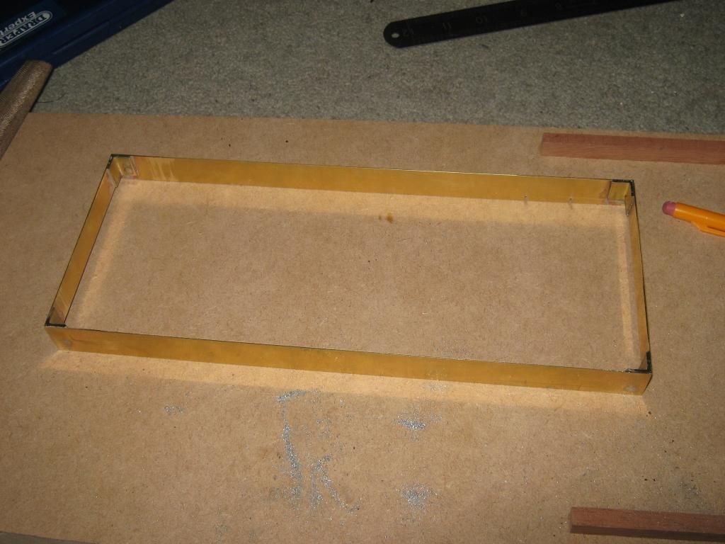 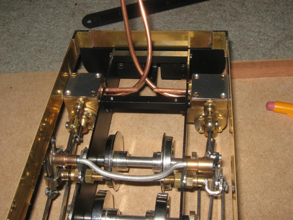 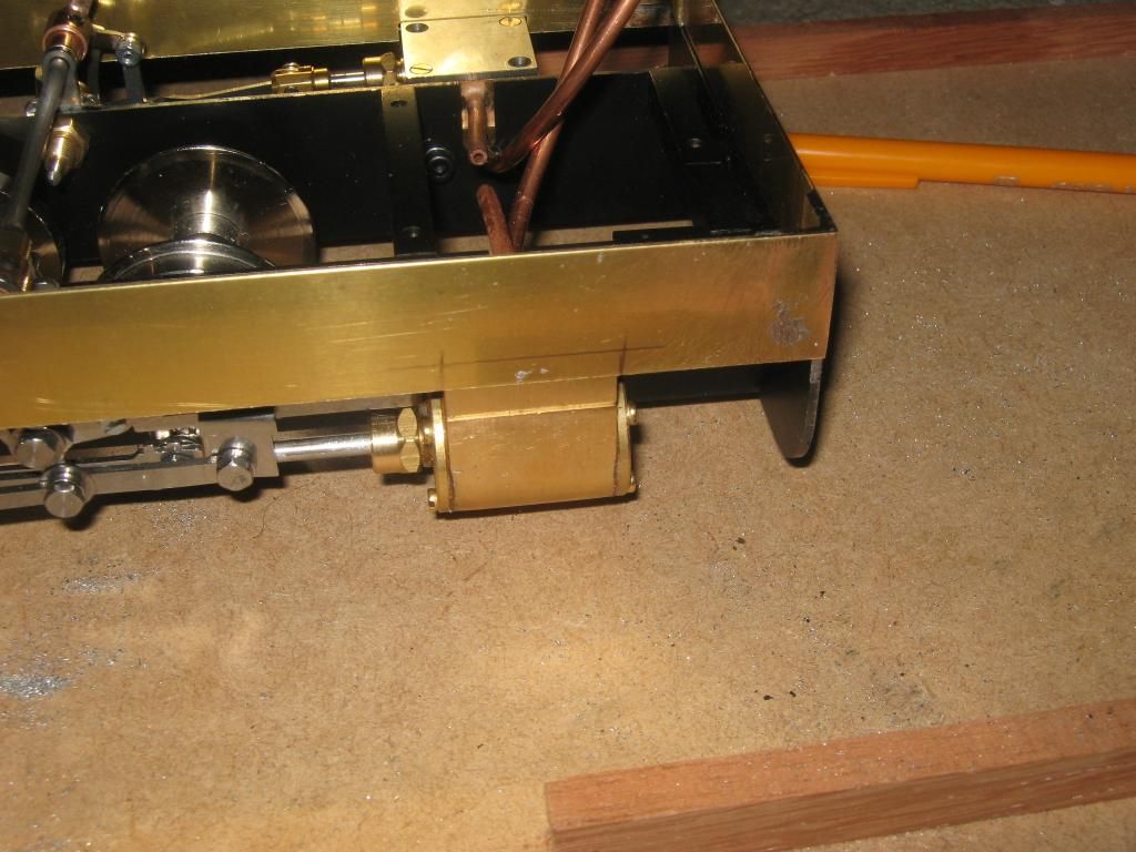 Next up was the floor pan. These would need to be made into two parts due to the linkage between the two sets of walschaerts valve gear that crossed the chassis at about floor level. There was nothing that could have been done about this without serious modification that I was not prepared to do, why ruin an already perfect and proven working chassis? A work around was found. 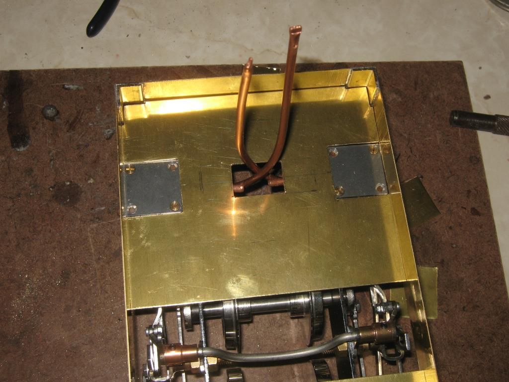 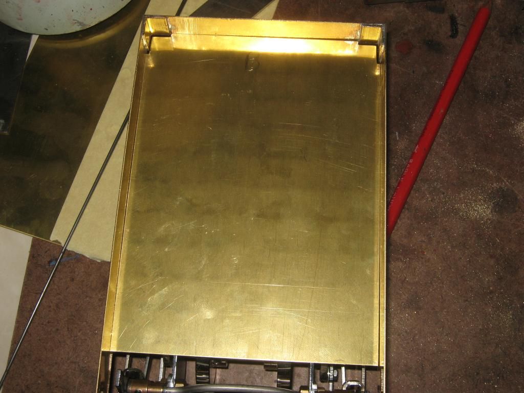  I had found some rather smart cow catchers from garden railway specialists that fitted the bill, they too needed some changing to fit the central buffer. The waste that was removed from the vertical rails, this was soldered in position to form the shape to tidy up the buffer area. 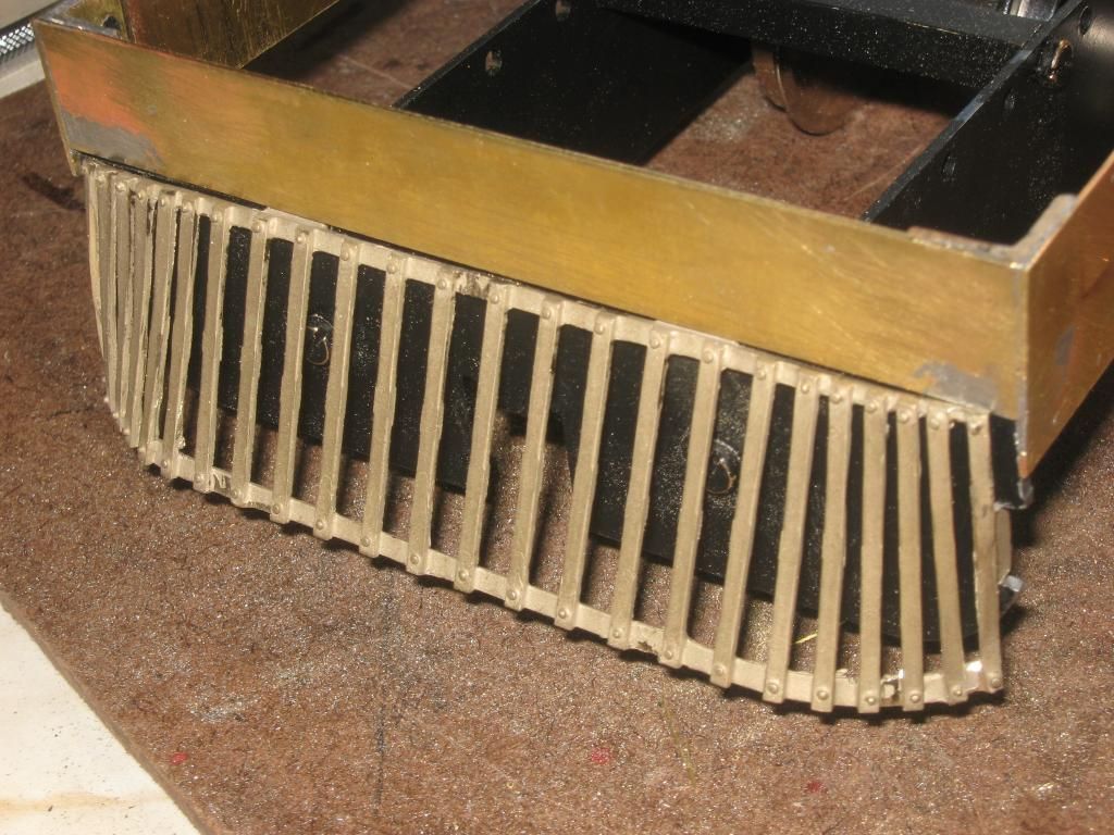 Next up I continued with the details for the floor section. Some steps were made out of some thin brass section and also the side plates with working flaps, partly for maintenance, partly for some 'skirt up' running to show off the motion 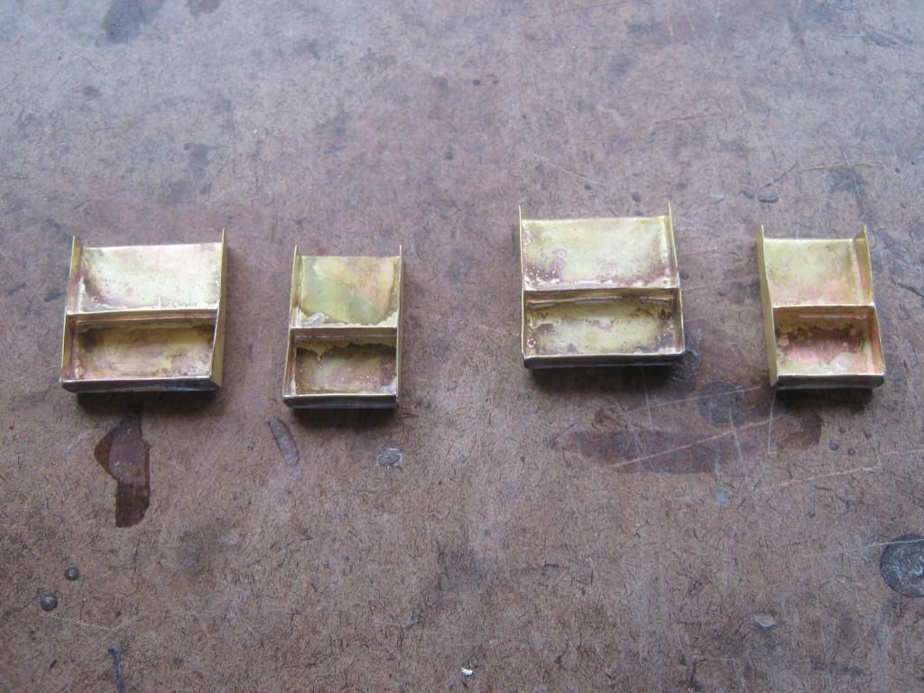 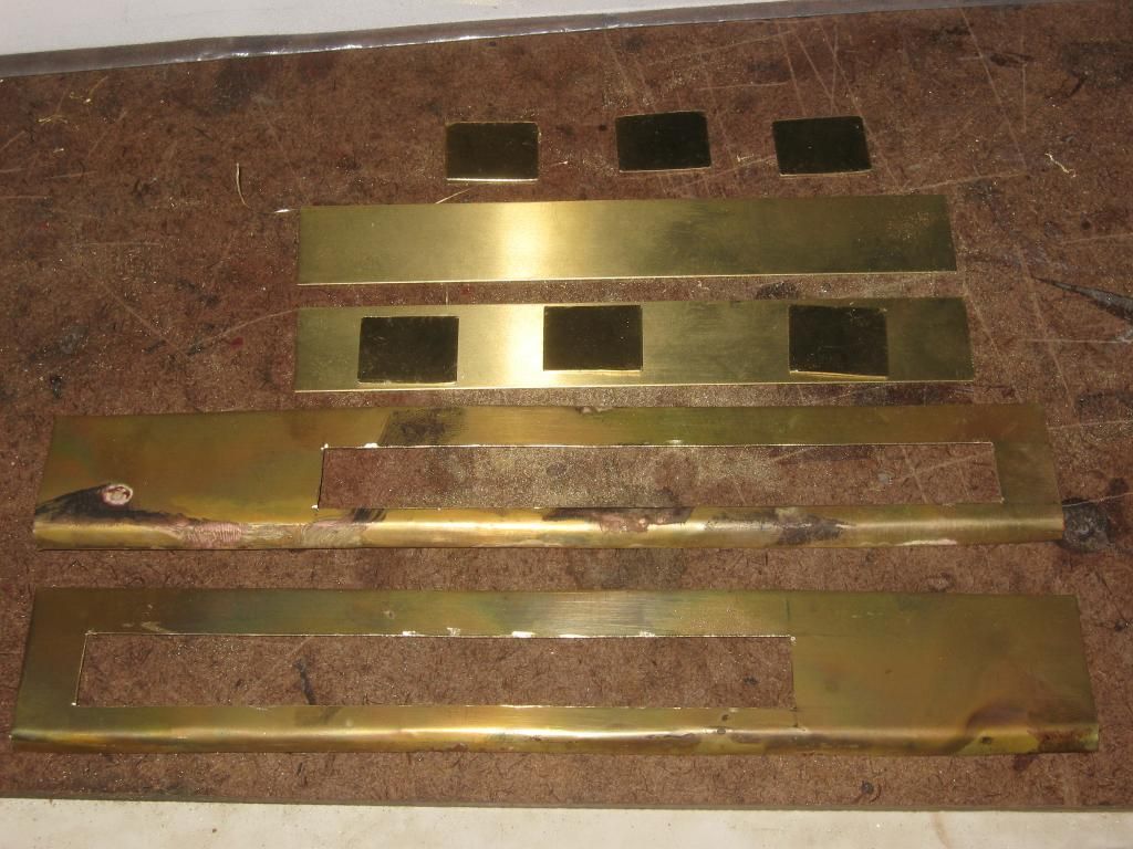 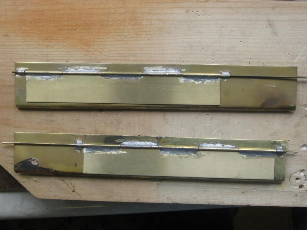 So with the floor pan part of the project nearly done (obviously it would need tweaking throughout the build process), It was time to start on with the body. It was a clear choice to use real wood for the body, it was wood on the prototype anyway and would be difficult to replicate wood without actually using it. Here are all the body sections resting on the floor pan for a mock view. 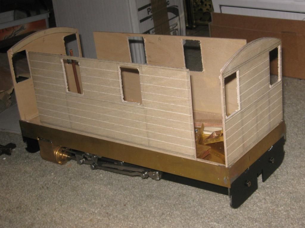 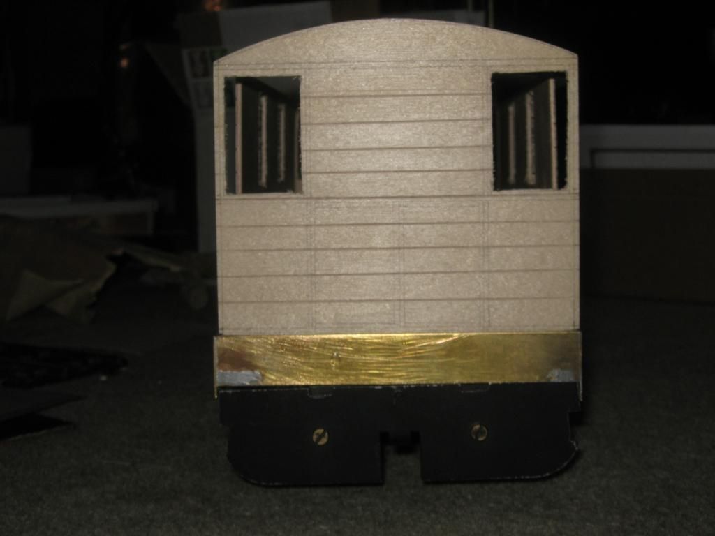 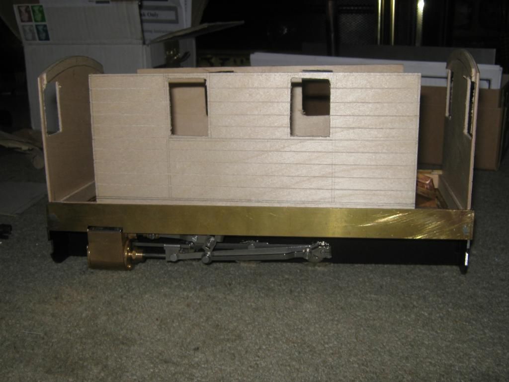 With the body starting to take shape I fitted the side plates on using some brass angle section and a dob of araldite. This was done mainly to temporarily fit the side plates until I could figure out what was going to go where in terms of height.  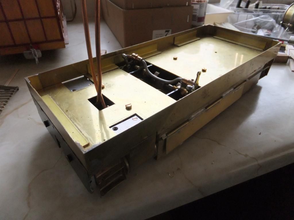 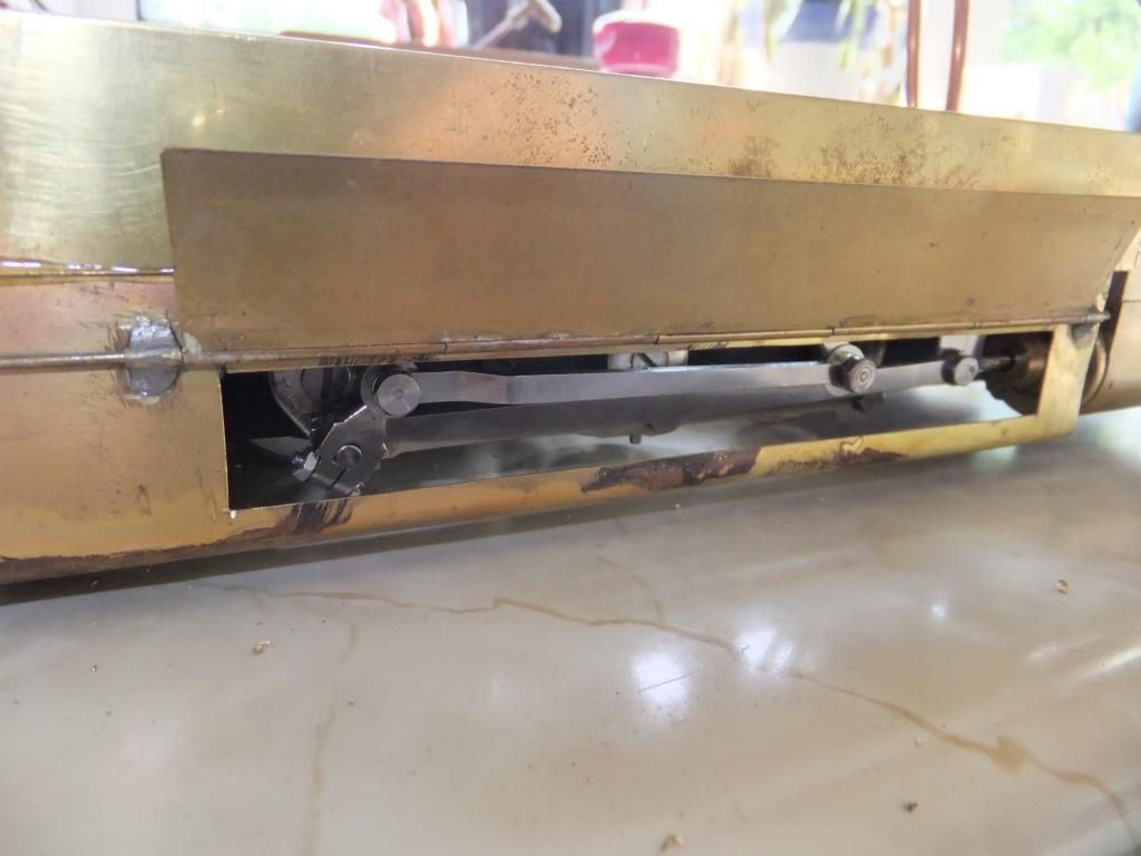 And now on with the body. First thing to come was to fix the body together so that the ply frame was one piece. Then the cladding could begin to add that 'planked' detail to the loco. 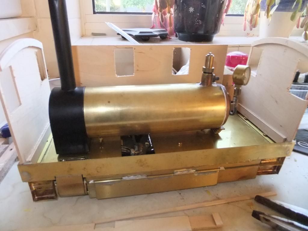 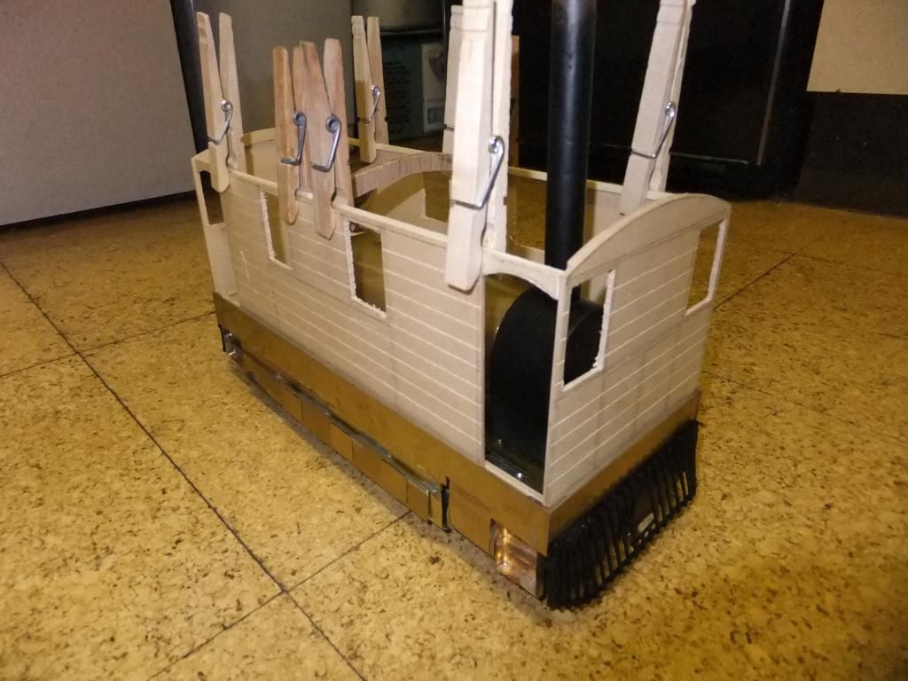 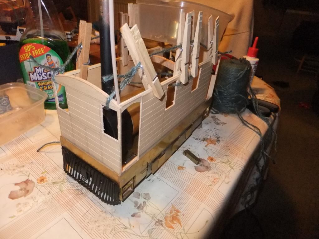 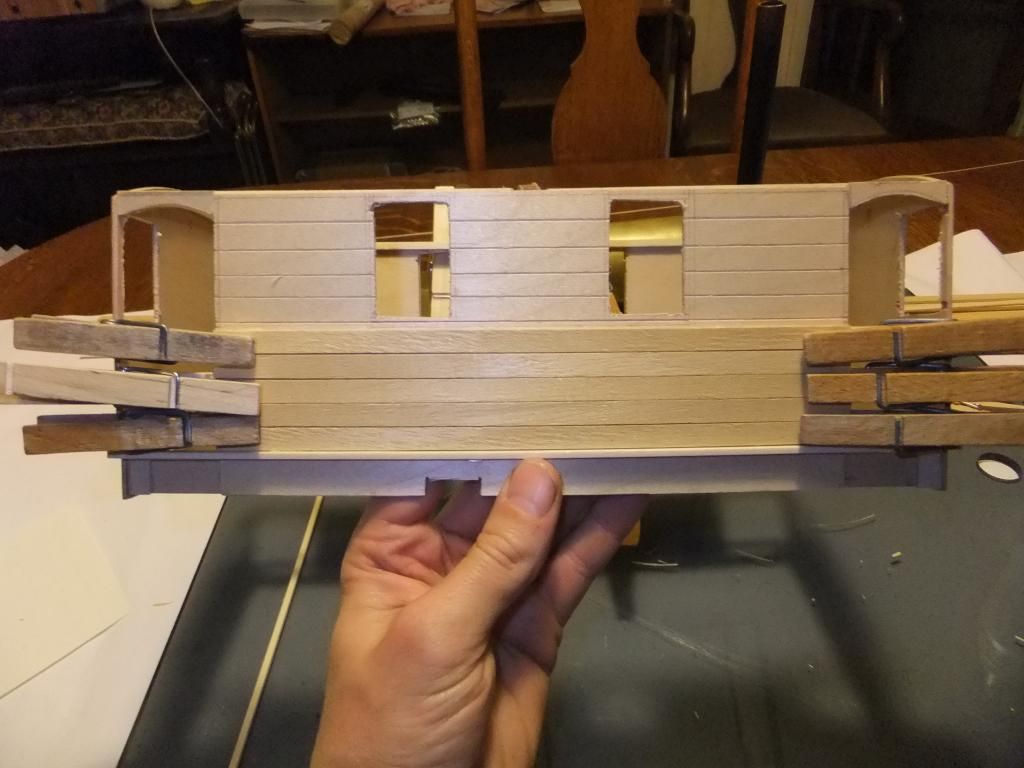  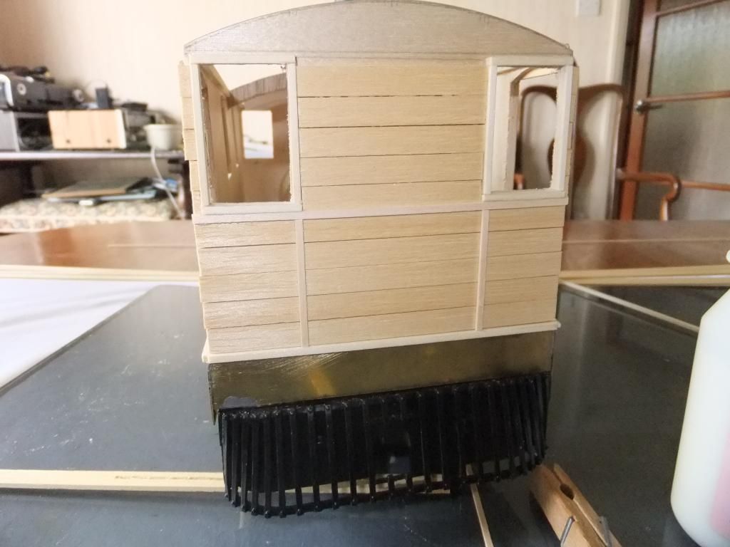 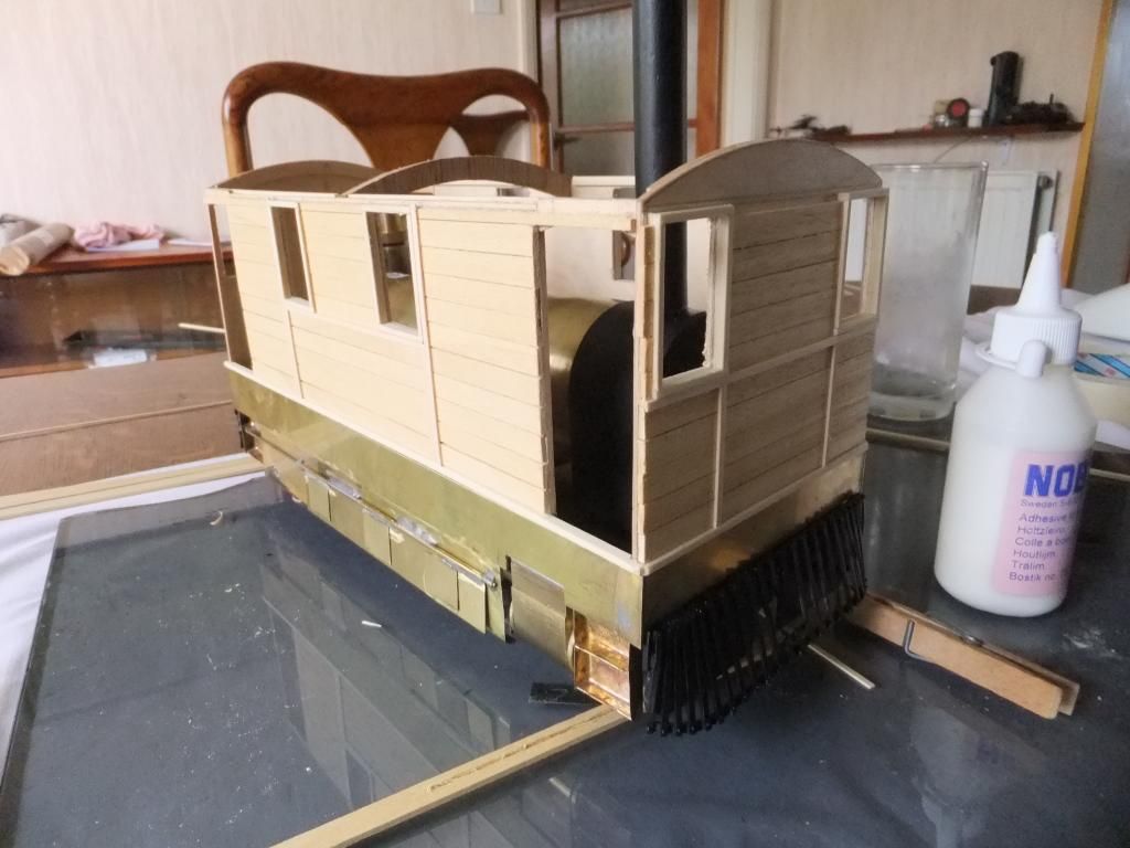 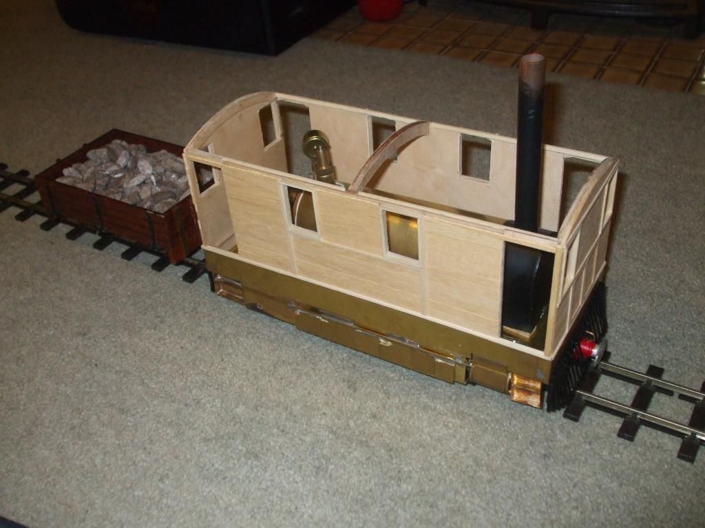 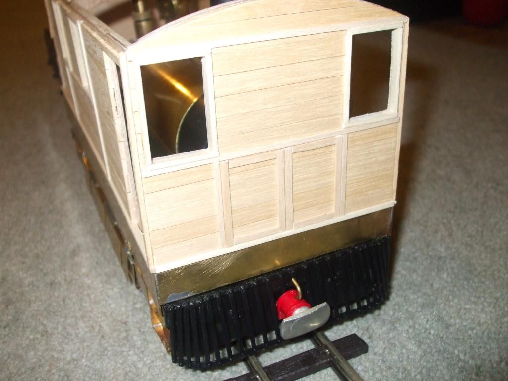 From this To this 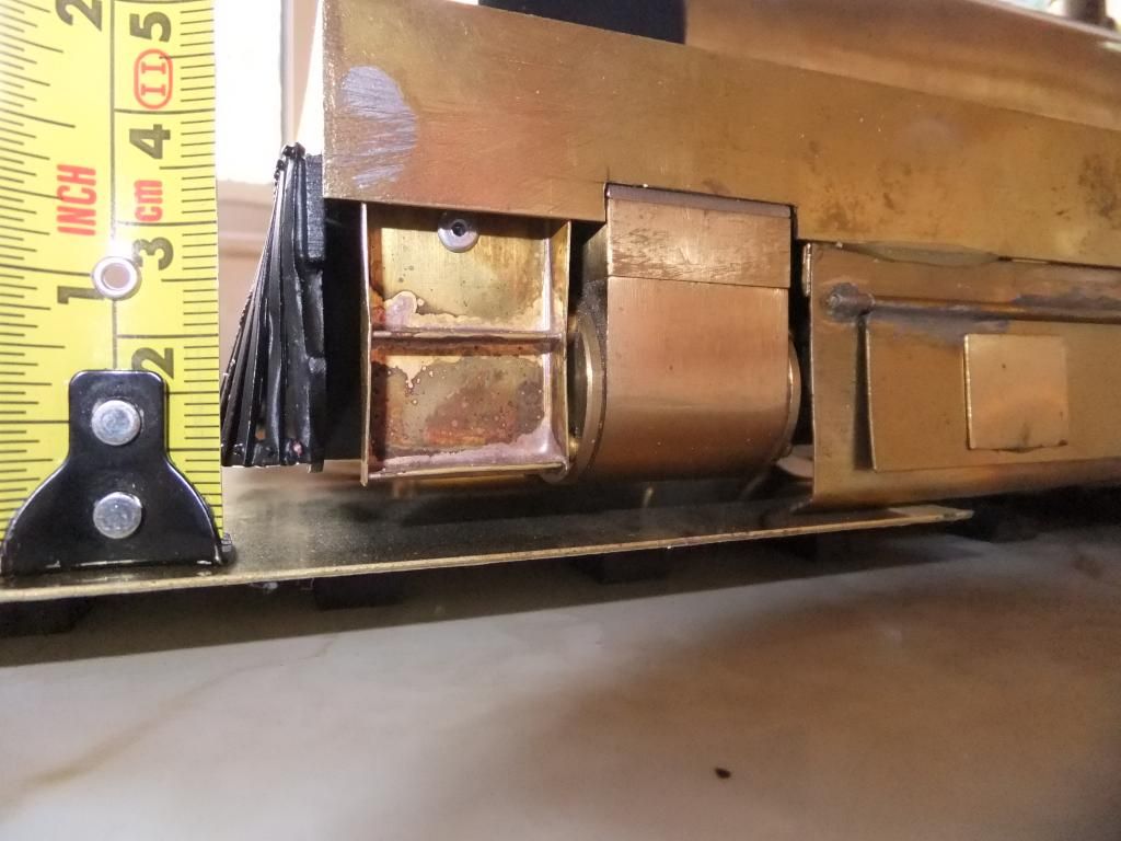 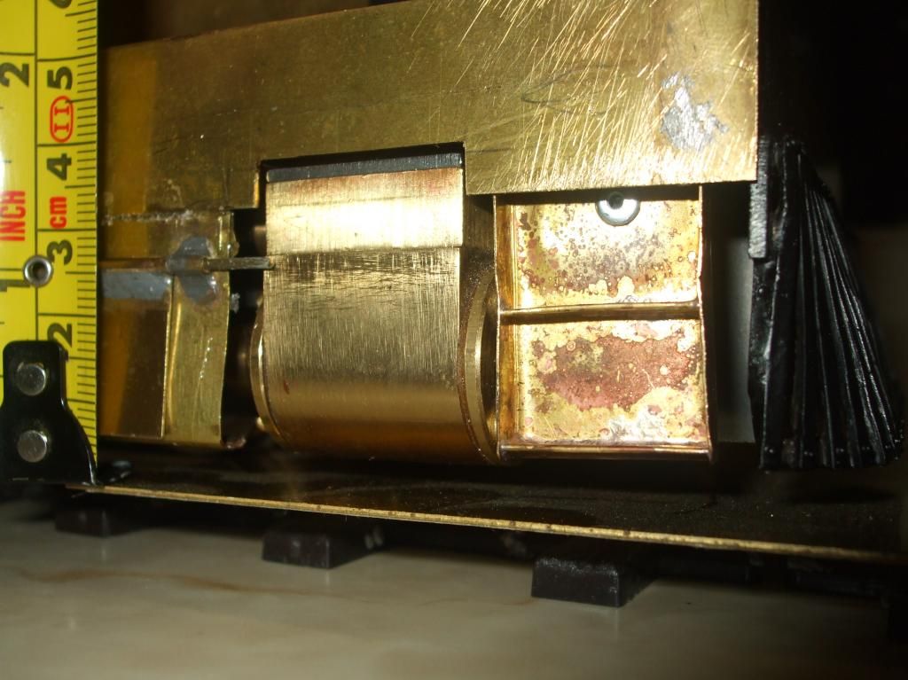 With the body built it was time to move onto the exciting parts. The boiler had it obvious location so the gas tank was located and piping made up. The gas valve was mad accessible by having it poking through one of the doors for easy adjusting whilst in steam. The decision was take to sink the lubricator into the floor. If there is one thing I hate it is mess on a model. At least the oil can drain from the underside of the floor without it protruding from the side anywhere. 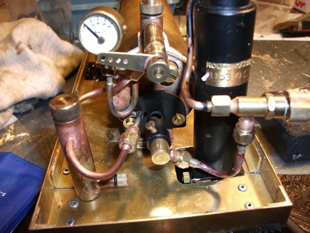 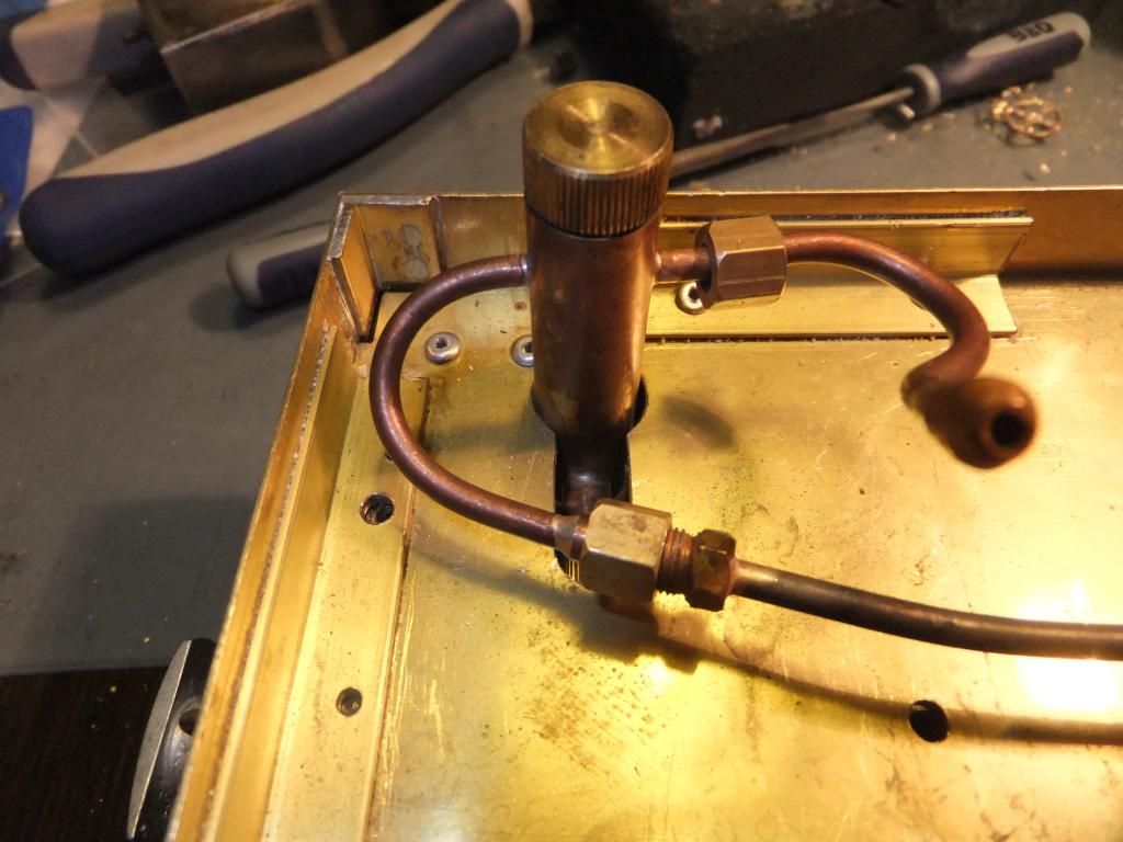 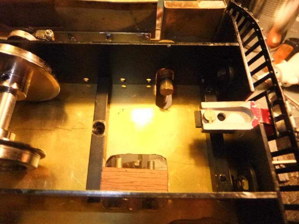 The first steaming So this was the big moment. I had a chassis that was able to steam, so what else could I do but steam her for the very first time! Take caution this video is a little lengthy and in places and a bit boring. It is a complete account of the first steaming of the now 'running' chassis with minor editing. Please excuse the uncut chimney, I was unsure what I was going to do with the top. 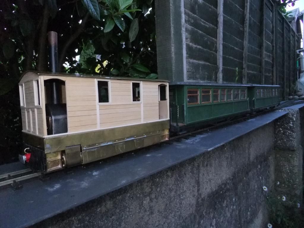 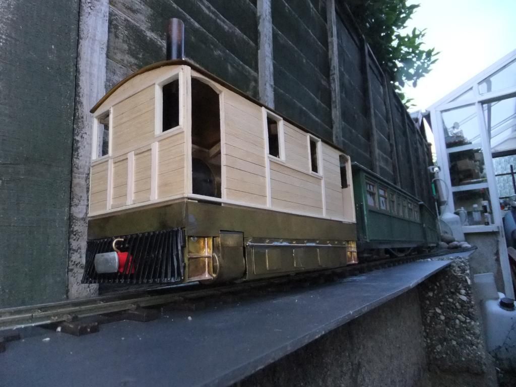 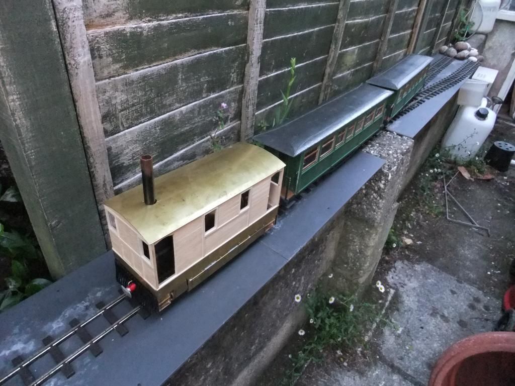 Now having had the steaming under her belt, it left me to take care of the finer points and details. The smokebox had some door, handle and regulator detail. The radio equipment was sited and tested and then the development for a better way for the safety valve to vent off was born. Eventually a coat of paint and servo installation was under way. The smokebox. The idea was put to me by a forum member elsewhere that I should detail the smoke box because it would be visible through the front doors. Having studied the J70 photos and obtained a book with a great photo with the top off, I stumbled upon the shape and door details that I was going to use. Then the smoke box door 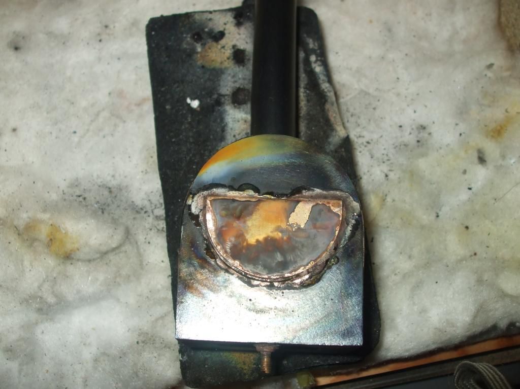 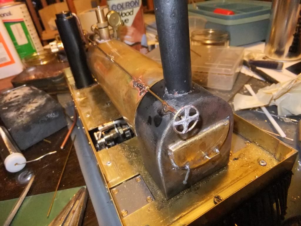 A last minute detail, a sand box Then the condenser. It was decided to silence the exhaust of the safety valve somehow because I hate the sudden blowing off of the pop type valves, so in effect the condenser would serve two purposes. I had some room under the skirt to house such a contraption, so why not use it? A small return was left on the saddle portion of the condenser so that excess steam would leak from under the skirts when blowing off. As it turned out this was quite effective. Here is a video of the condenser working The gas was turned up very high in this video on purpose to try and get the safety valve to blow off as much as possible and make the most noise it would do if on the line. Here we have both servos linked up in situ. Direction servo with linkages  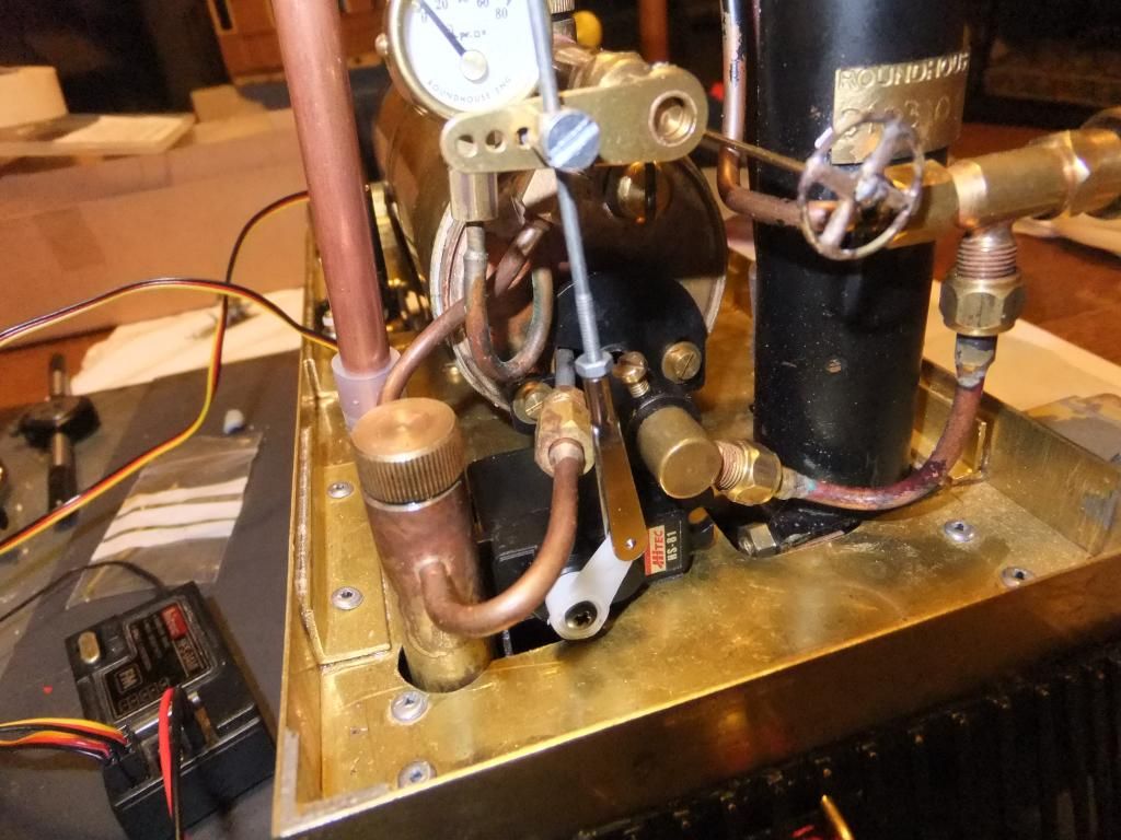 Regulator servo and linkages A quick video to demonstrate testing. And at long last a first radio controlled run (with a trimmed chimney) 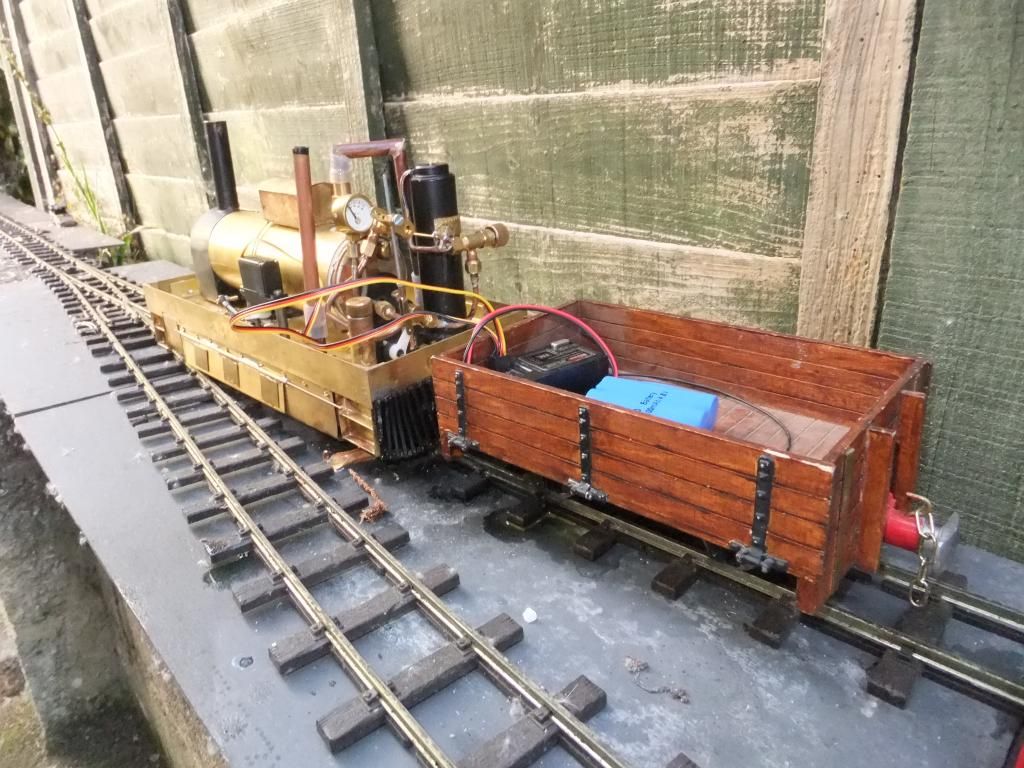 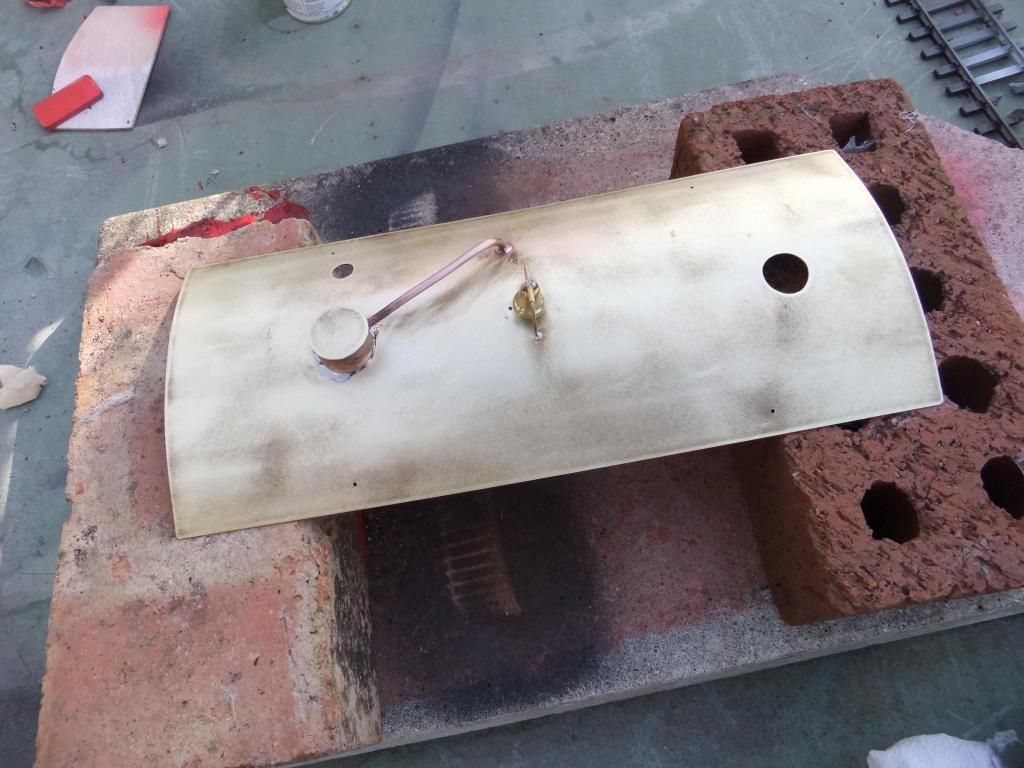 The Roof was easy enough. I cut the shape out of a sheet using a guillotine and soldered a few details on top. A dummy safety valve take off and a bell. The little bell was given to me by my six year old daughter from one of her toys, how very sweet and kind! :-) At last, painting! The time had come to get on with the finishing touches now the loco was in the process of running in nicely and the little problems had been shaken out and overcome. So without further ado; prep, prime, refinish was the order of the day. 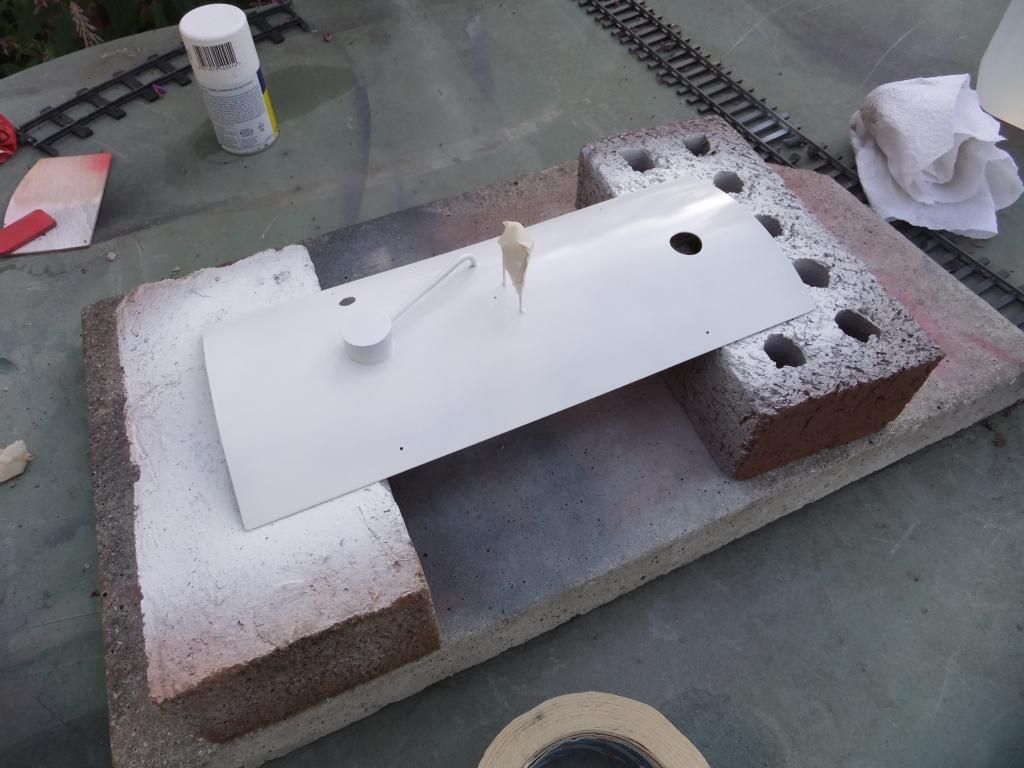 The roof in high build primer after a coat of non ferrous compatible primer (there is no point using ordinary etch primers on brass, not many people know that). 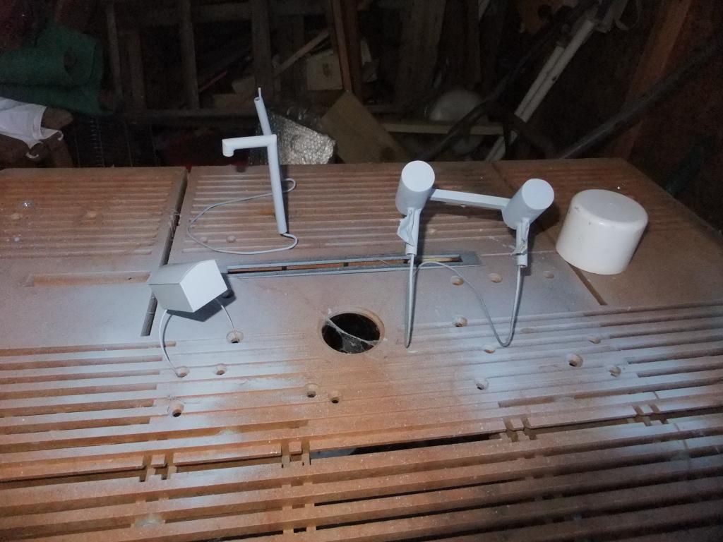 The detail parts. Condenser, Safety valve take off and Sand box all in etch primer. Not alot of point in making these parts like glass, no one is going to see them all that well. 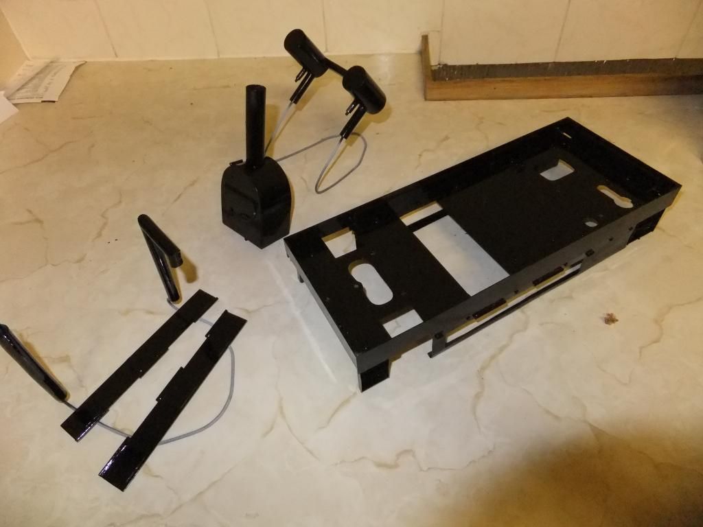 All parts painted in 2 pack automotive paint. At least I know it can take heat and is really durable. Final assembly With a few things l eft to tweak on the build, I set about final assembly and doing the small add in details I thought about using when disassembling. I decided to add so 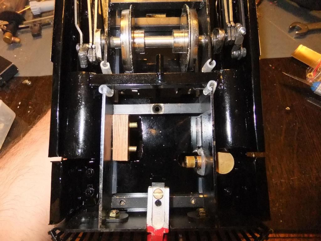 Although it is difficult to see, here is the condenser tanks fitted snugly either side of the main frames, note the saddle link and drain just behind the rearward axle in the centre. As you can see there is plenty of finger room to drain the lubricator. 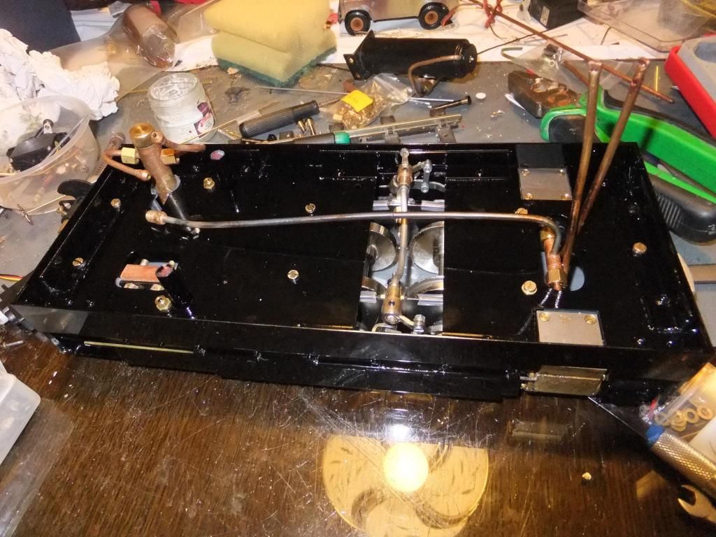 The main floor man mounted on the chassis. 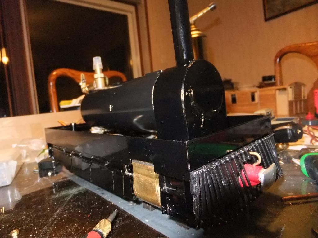 The boiler mounted, I just need to pick out the smoke box details. 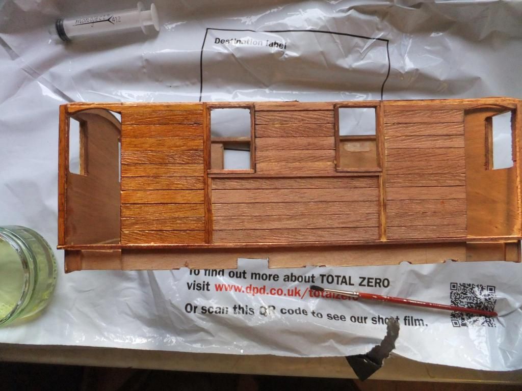 With the metal parts finished, it was time to turn the the wooden body. After staining in a suitable colour I brush painted some 2 pack satin wood lacquer on. The lacquer really brought out the colour of the staining. 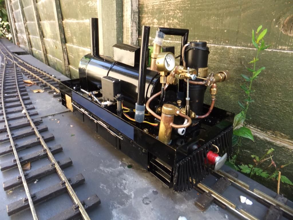 And that leaves all the big parts done. The working parts of the loco are finished, that just left a couple of fiddly cosmetic details to add on. 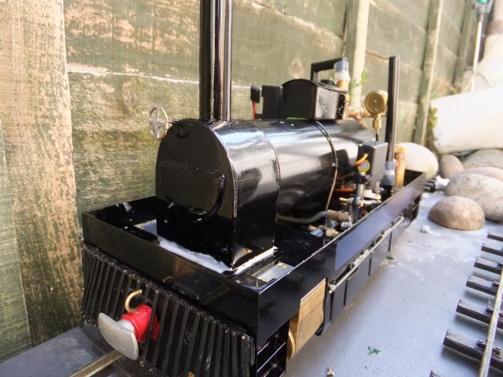 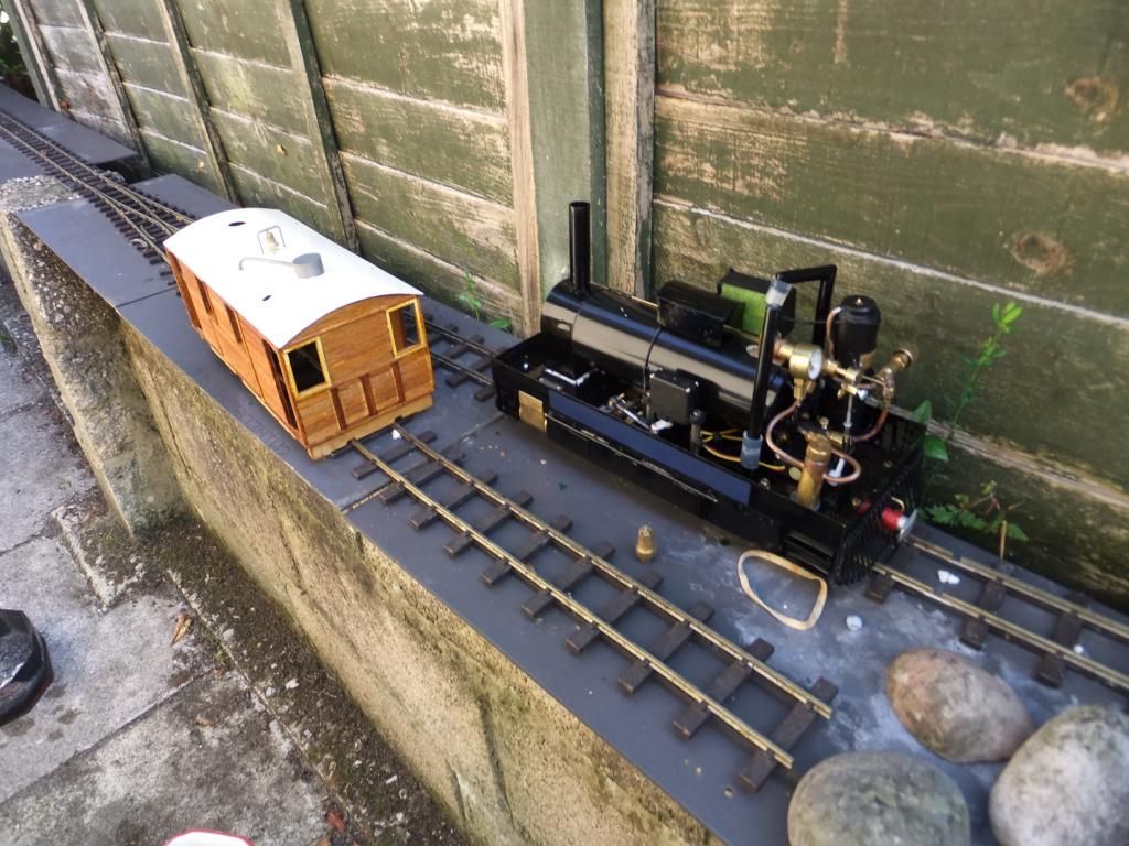 And a little inaugural run. 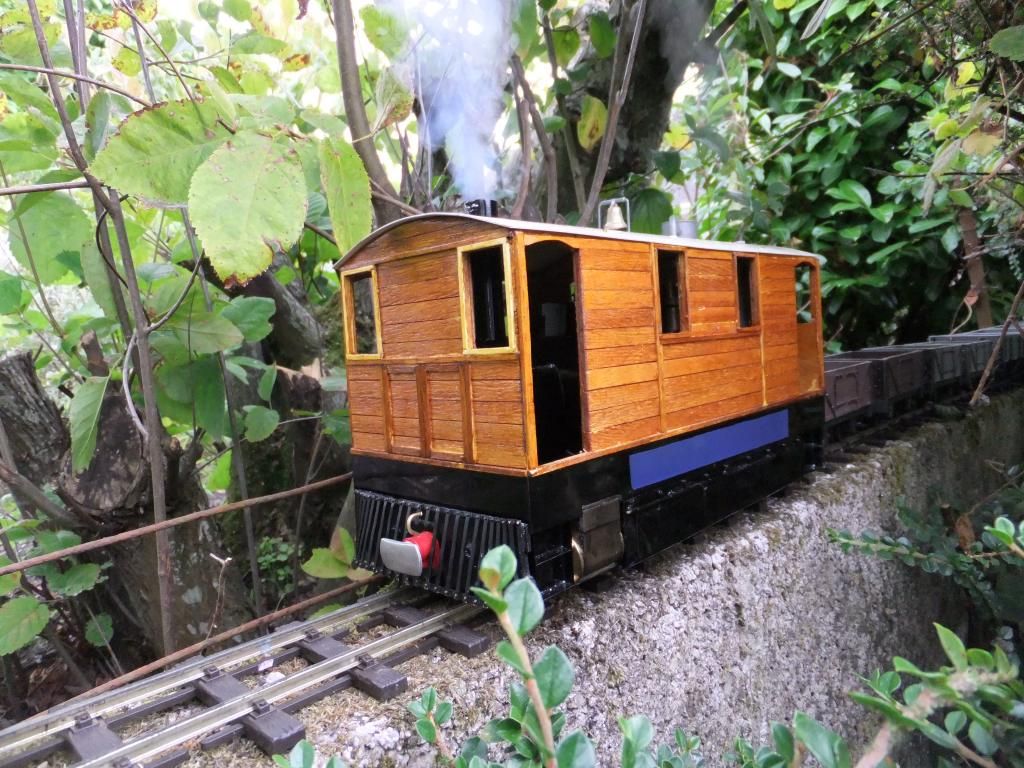 I blackened the cylinders down with some grate polish. It is a shame though because it just wipes off. I could do with a more permanent solution without painting. 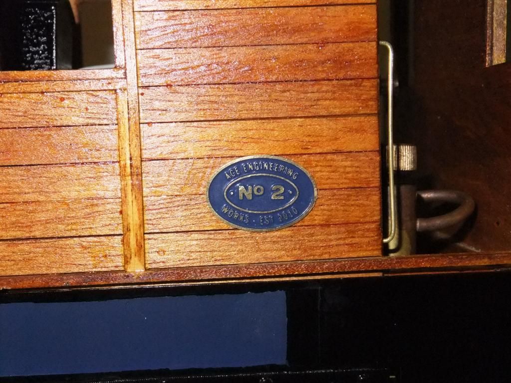 Shortly after the inaugural runs I added some custom engineers plates and also some small hand rails. 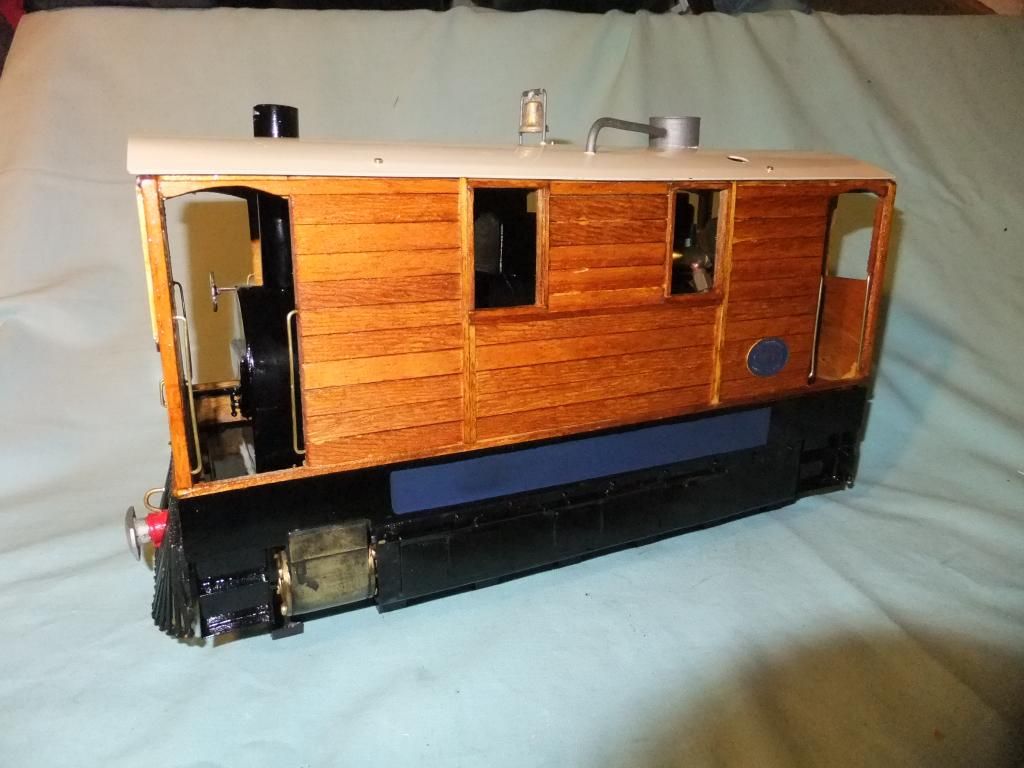 Tram on the travels In September 2013 I took the tram (still unnamed) to the Elsecar heritage centre for the model steam show. I met up with some fellow friends and we had out first run on club rails. 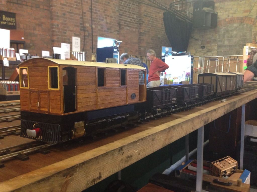 Someone was kind enough to lend me some rolling stock to use whilst I enjoyed my first ever public run with a model steam engine. As I was in the area one of my friends invited me over to his line in 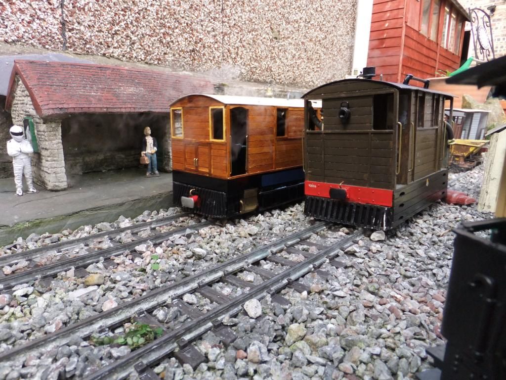 After visiting the Woodrow Light Railway it was pretty much decided that I would call the tram 'Suffolk Punch'. The name came from one of my favourite working horses and the tram has characteristics of being a hard worker and very strong. 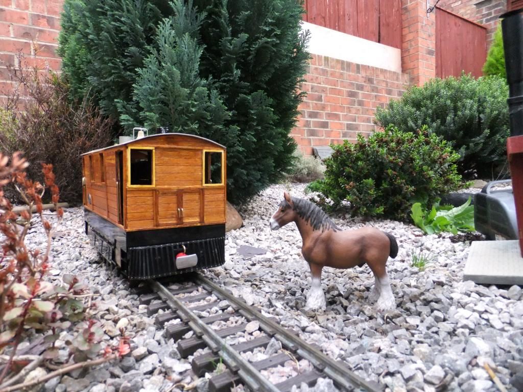 Suffolk Punch meeting a Suffolk Punch? Here is a video of the account. I apologise about the music, it was joked about at the time. I apologise about the music, it was joked about at the time. Then fast forward until November 2013 when I went to the Exeter Garden Railway show hosted at the Matford Centre on the marsh Barton Trading Estate, in err..... Exeter? 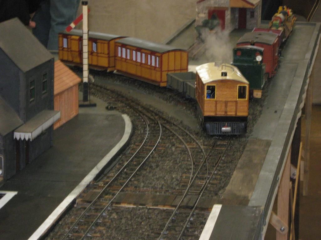 Here we are running on club rails once again. I met with some other forum members from various places and had another great day. Here I met Chris Bird for the first time and Roy Wood and spend far too long talking to them both (they both had work to be getting on with). Chris kindly had a look at the Suffolk Punch and sold me a chuff pipe to use and we spoke at some length about how to quieten it down a little. I didn't want this tram to bark away like a normal locomotive because they were meant to be quite quiet, so as not to scare people and horses along the roadside. 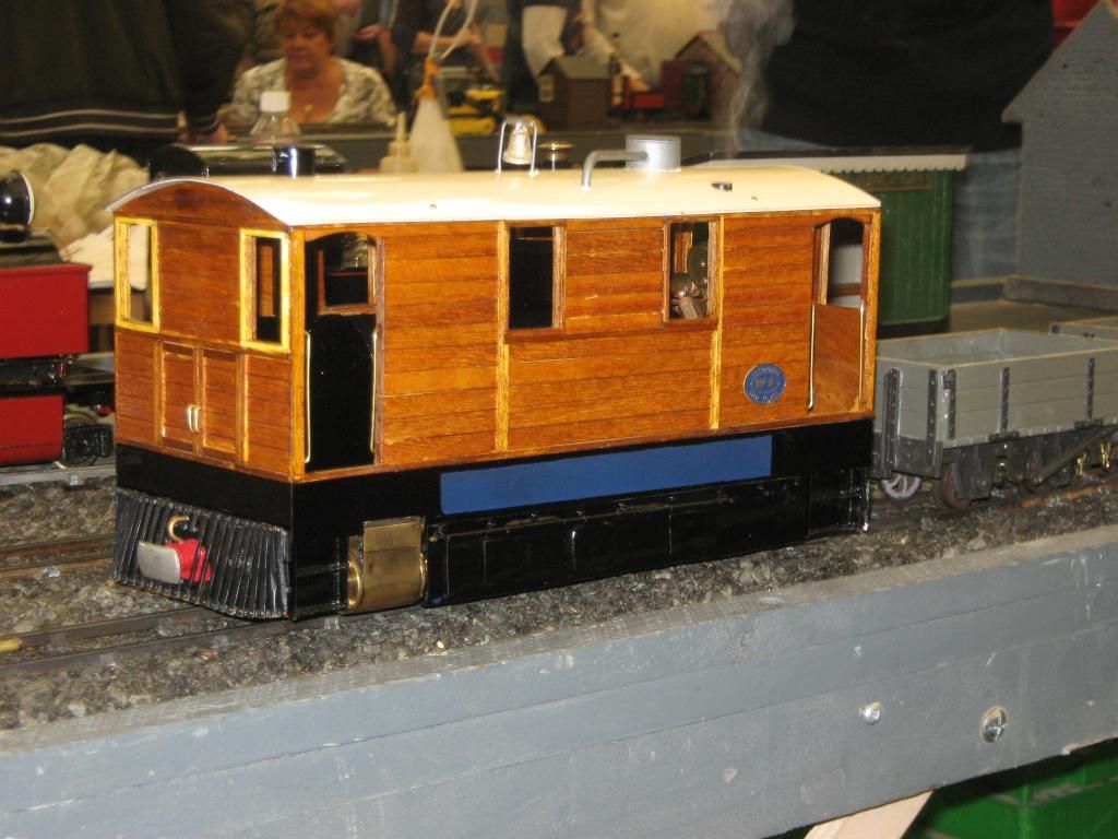 Once again I found I had a wonderful day, (could have done with two I think) and met some great fellow modellers. 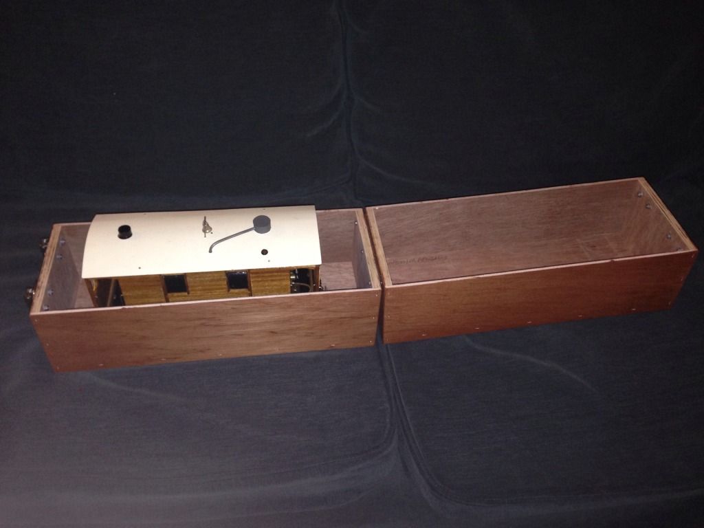 When I was at the Elsecar model show I ordered a travel box for Suffolk Punch, this was going to be of a custom size from 'Locoboxes'. Very helpful people and kindly brought it with them to the Exeter show for me to collect. I just need to add some track and buffers inside for some safety. 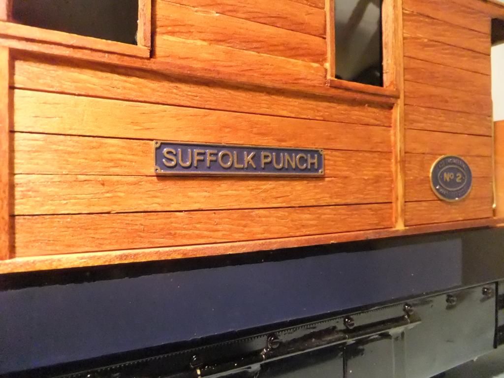 At last some nameplates! Now that does look nice. :-) 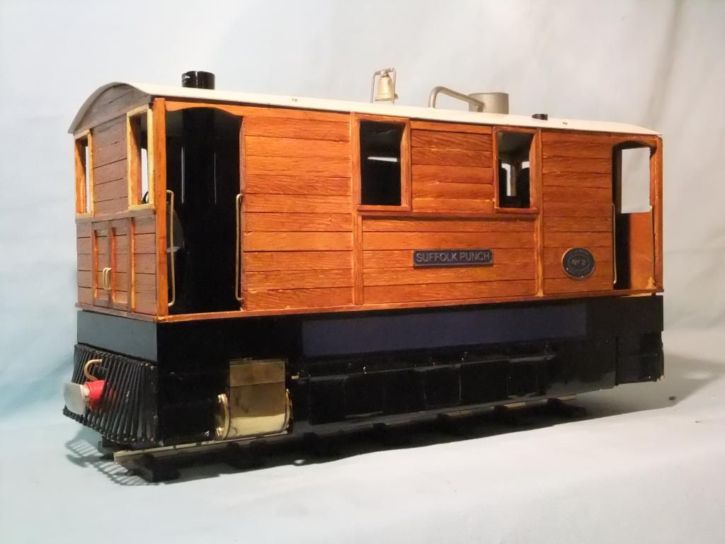 Now things were really starting to come together, and I was altering the timing every now and then. She seems to run better and better! 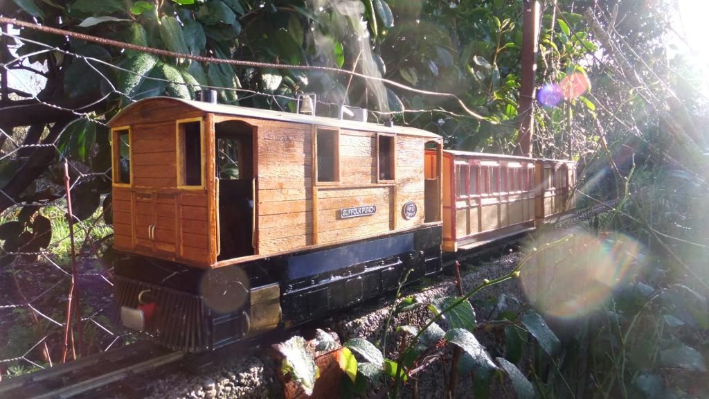 The first steaming of 2013, sporting the new plates and almost running light with a pair of Brandbright freelance coaches. A new modification Whilst browsing one of the model steam forums I found a nice little modification for the gas valve. It aids in fine control and also gives a much better reference point for the position. Not to mention it hides away the gaudy looking round knob that I had in the right rear door. 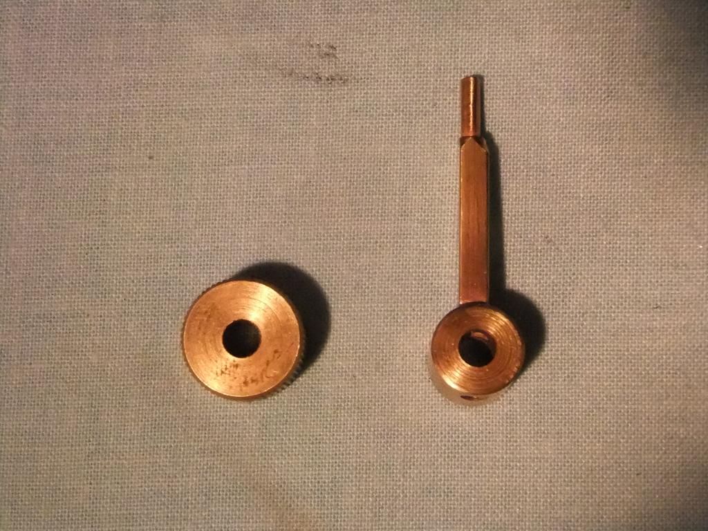 The new lever next to the old knob style gas regulator. 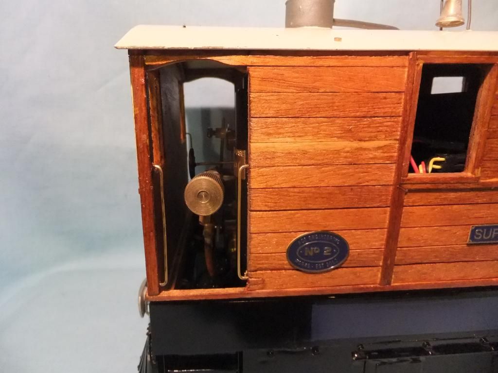 The old style knob looks horrid, but the new is hardly noticeable in place. 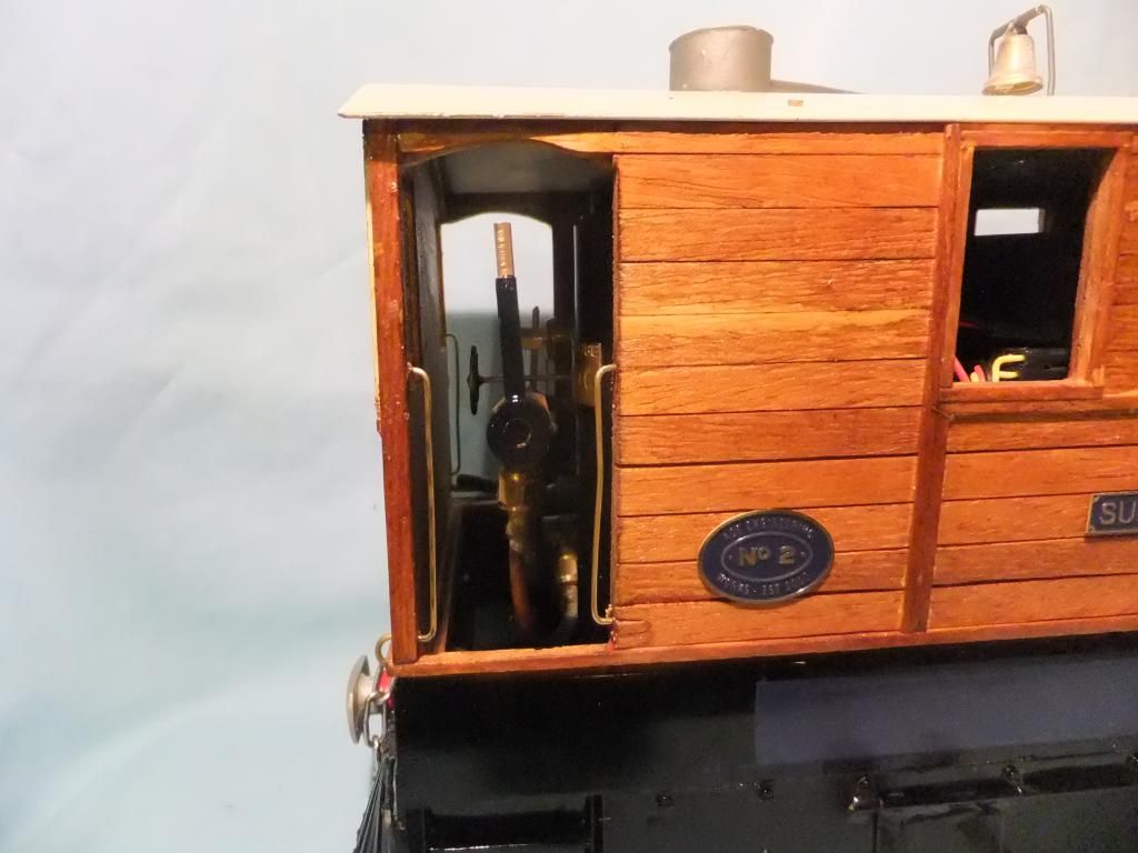 Here is the first run of 2014 on a beautifully still cold morning Future DevelopmentsAnd that pretty much concludes the trams current travels and running for now. I am in the throws of designing some rolling stock to be lazer cut and assembled for Suffolk Punch. It seems quite difficult to find anything suitable for her being a standard, posing as narrow gauge locomotive. The plan is to build six coaches all together, two bogie coaches and four, four wheeled ones. More to come as developments are made. |
Locos >