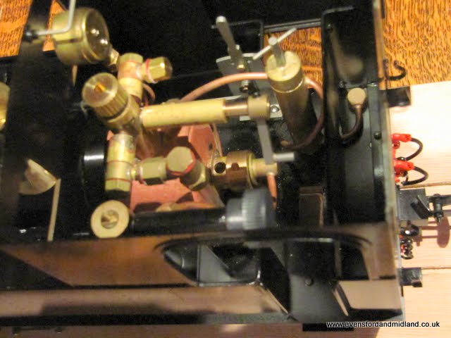
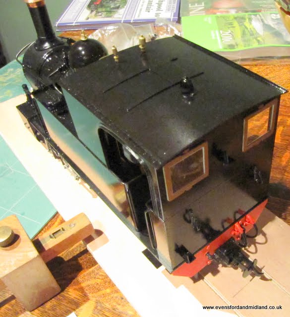
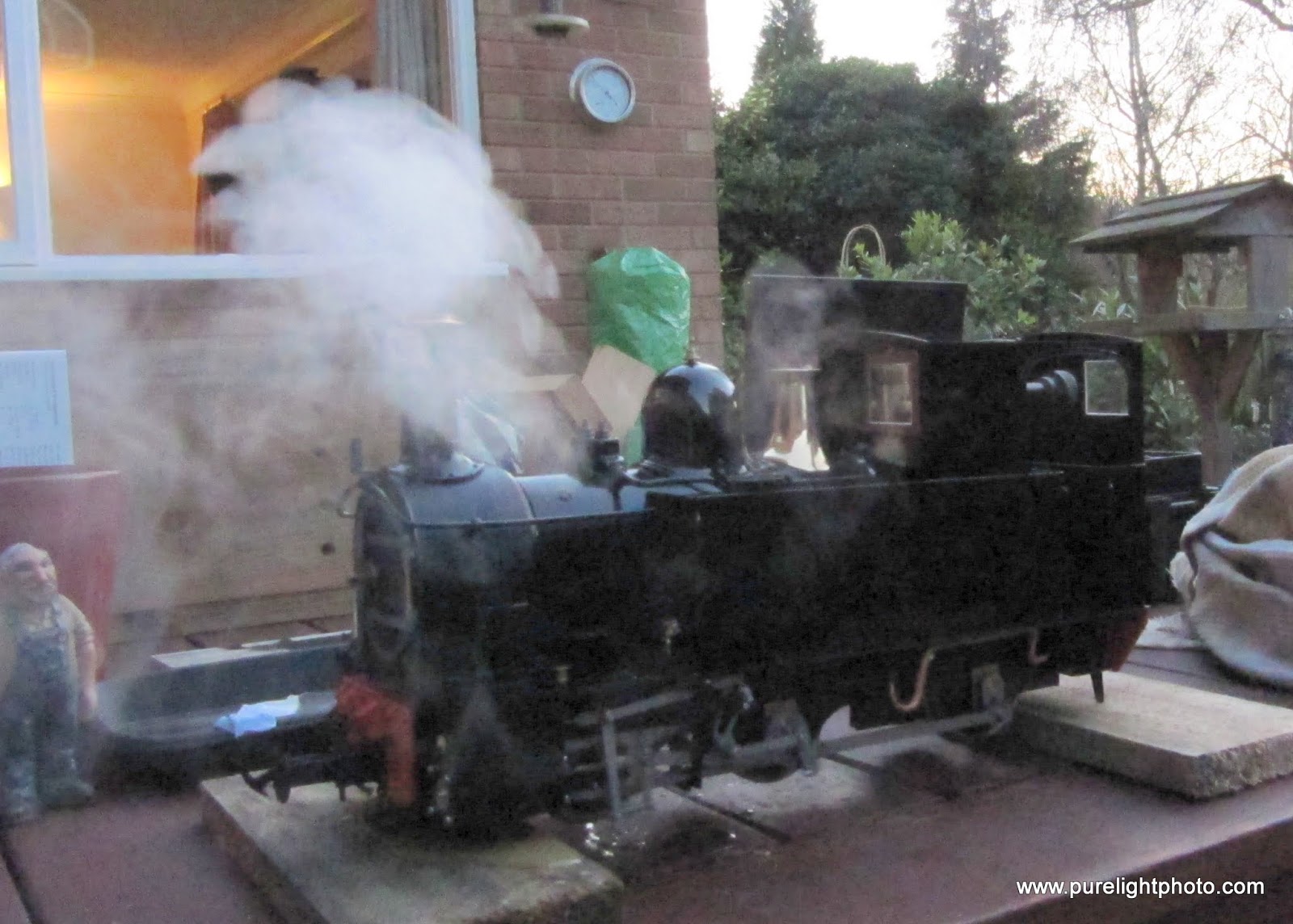
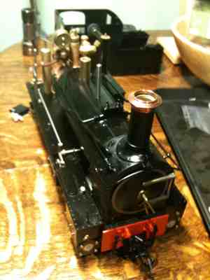
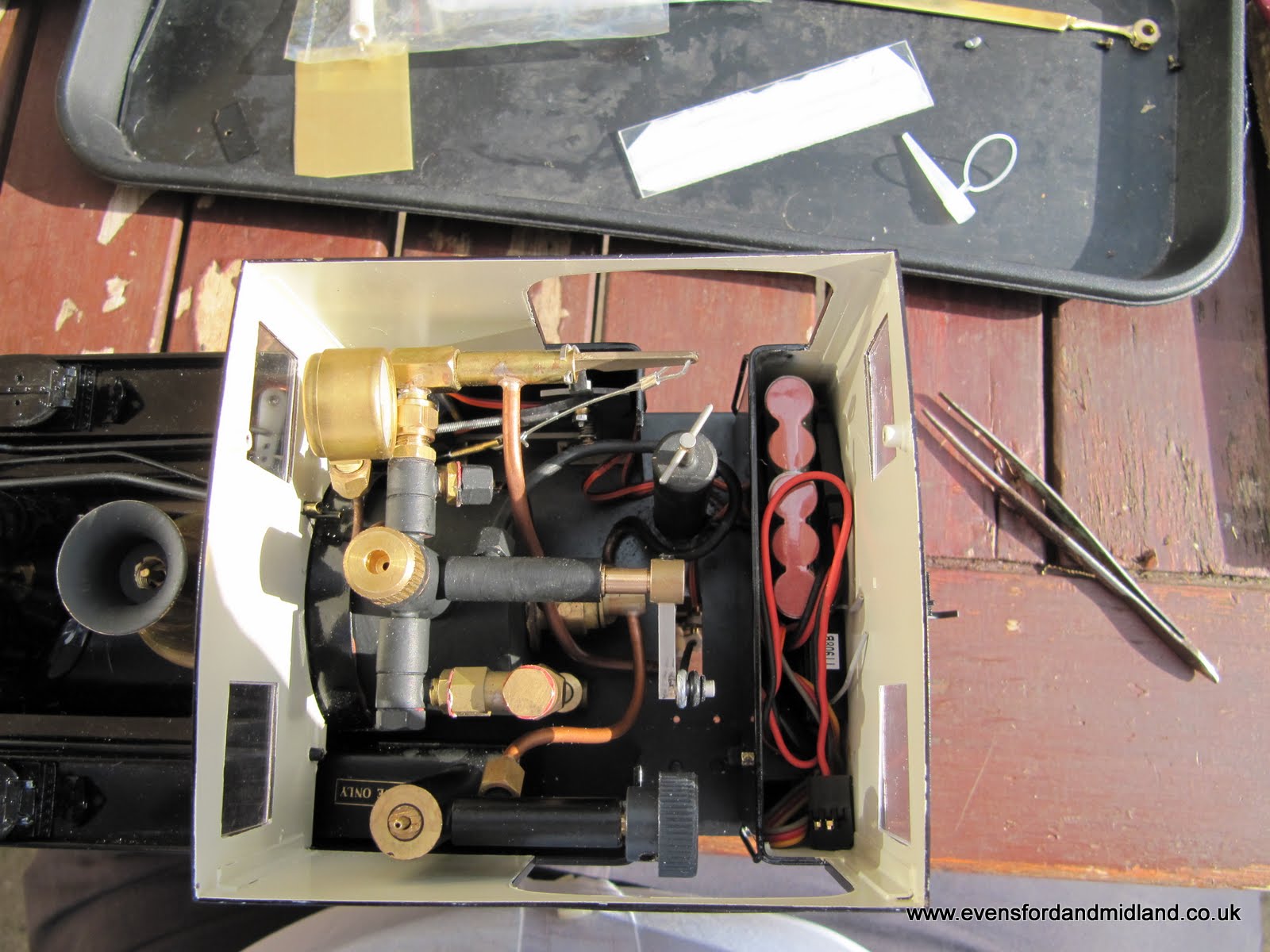
Not the best picture but it was on the kitchen table.
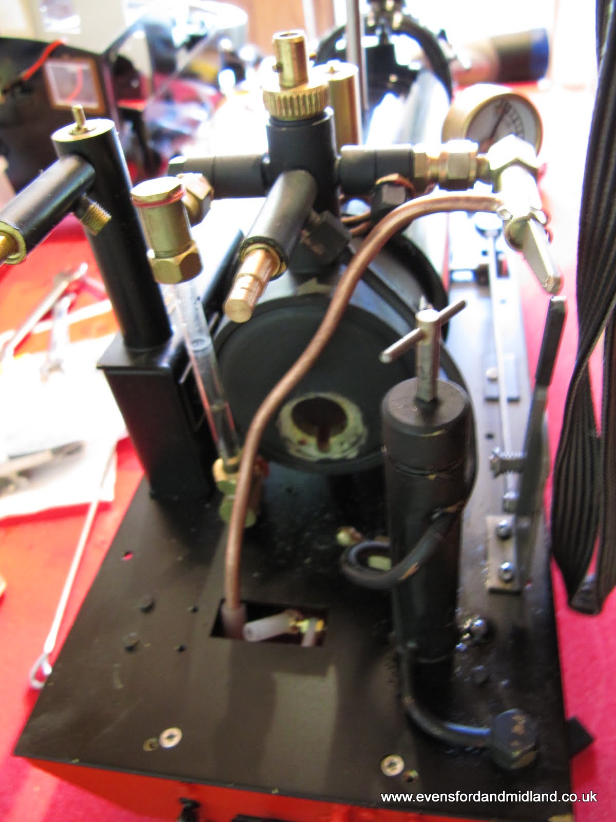
Some interesting changes in the cab when compared with the Lawley and Caradoc.
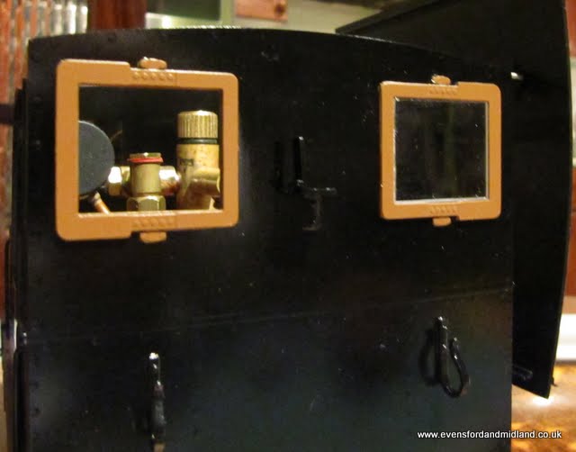
There is a Bunsen burner-type collar on the burner, presumably to adjust the air flow. The sight glass is very long. There is an interesting fitting on the pressure gauge banjo with a blanking nut on it. Not sure what that might be for. Any ideas?
Oh and joy of joys, the boiler is lagged. That must help with length of run.
There is plenty of space in back of the cab (presumably in what is really the bunker) for batteries, receiver and a switch. Underneath there is a load of room for a couple of servos. One for the regulator and one for the whistle (if I go that way). The DJB whistle has to go under the footplate apparently and I'm not desperate for a cloud of steam to appear under the loco every time the whistle blows. Don't really want an overscale whistle on the front of the cab either. It's fine on the Lawley and Caradoc but it wouldn't be right on the Earl somehow.
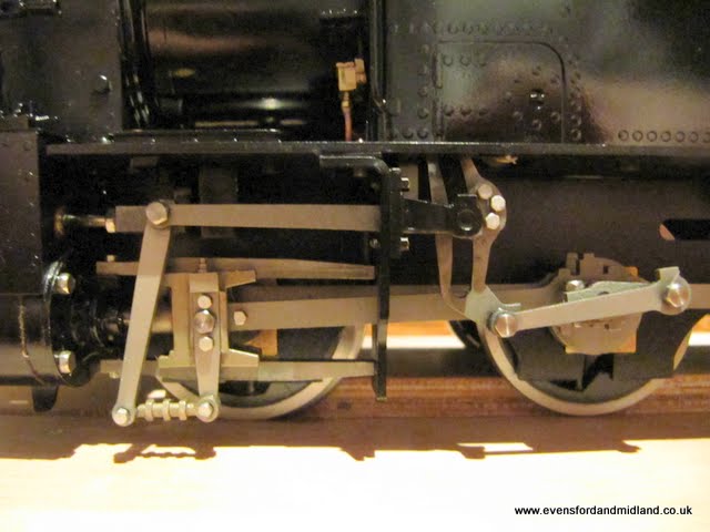
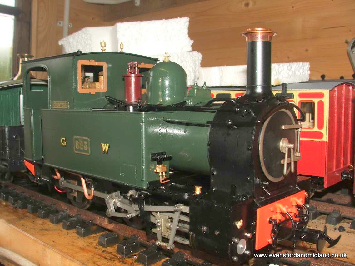
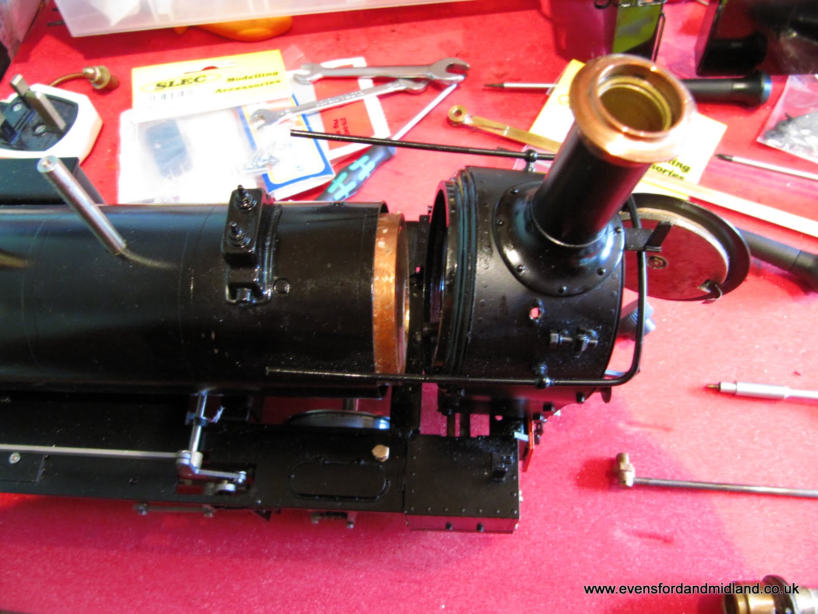
It's my first steam loco with any sort of valve-gear outside and I'm liking it a lot...
I know somebody is going to tell me what the gubbins is on top of the dome (I hope)
Appearance
Glazing the spectacles
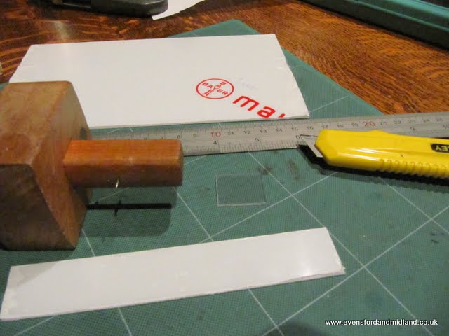
The big square windows needed some urgent glazing. One small piece of polycarbonate, a gauge, sharp knife, etc. They need to be a good tight fit so no glue is needed.
Makes such a difference. Had to be done before bedtime...
I do wish they could be opened but it looks like they are part of the cab.
Close-up of the spectacles (do you still call them that when they are square??)
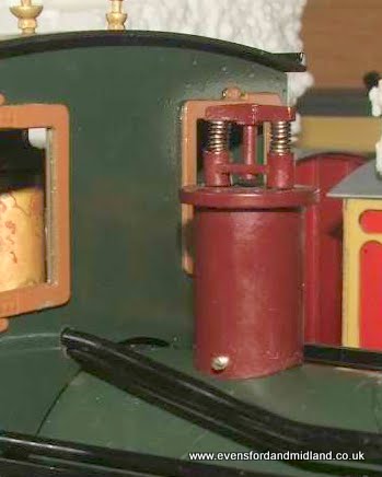
Safety valve cover
Now I don't want to upset all those GWR fans and I do believe the loco looks cracking as built but really, the GWR safety valve cover on the EMR? What would the Midland General Manager, Sir Guy Granet, say if he spotted it??? I don't need that discussion...
So some changes are under consideration. The good bit is the safety valve cover comes of very easily (too easily some might say...). So James (midwalstokie) has kindly provided some pictures of his Countess with a temporary fitment of the cover from his Superior.
I am now trying to find out how I can buy one of these.
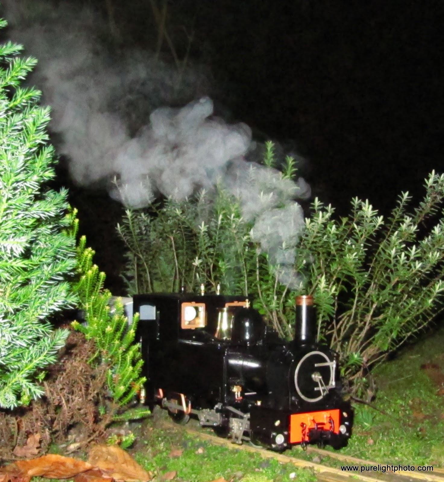
In steam at last. Been here four days!
At Short Wood on a the running in turn.
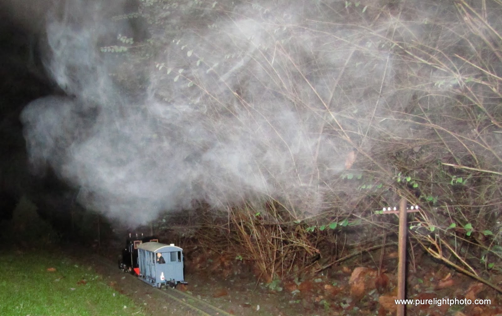
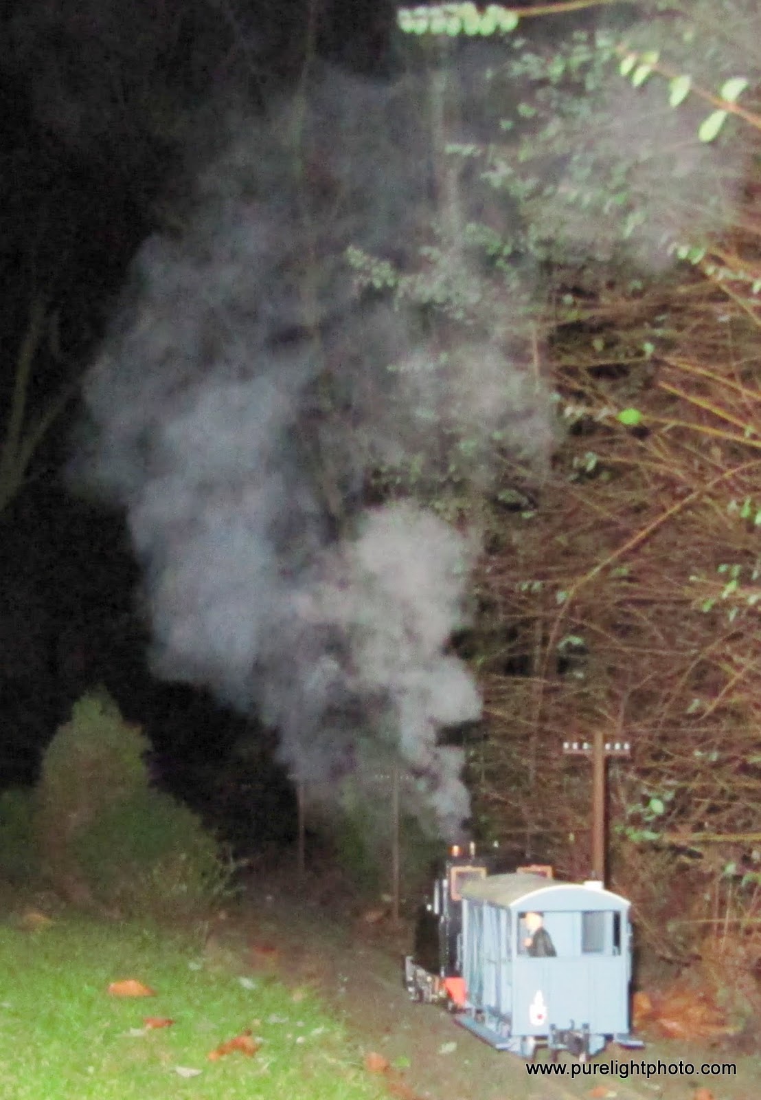
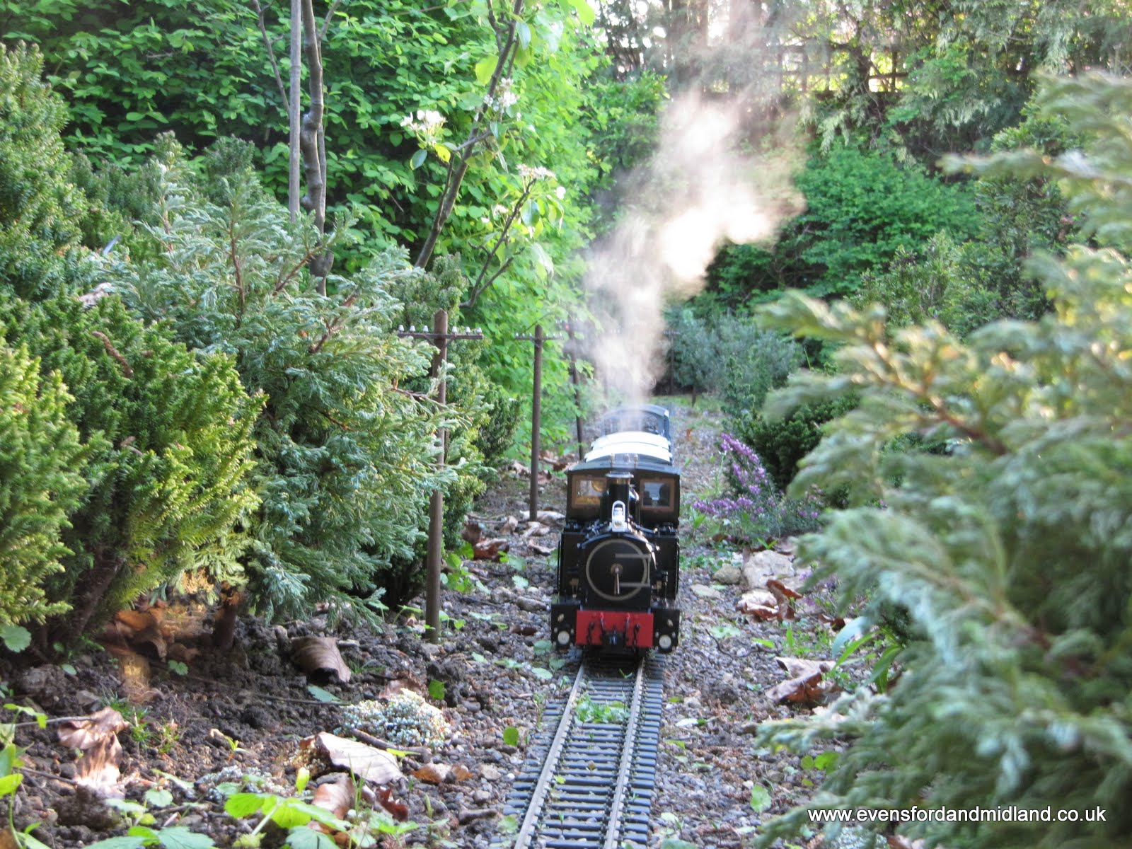
Steaming up the bank later on in the dark at zero degrees C
Lots of steam
Ran about 40 minutes, maybe more (can't say exactly) and was very low on water at the end. Wonderful. The chuffer is great too.
Radio control
Ran about 40 minutes is about right, and that was only me chasing the loco round the garden. Radio control is essential for me. I know others couldn't bear it but I feel so much more connected.
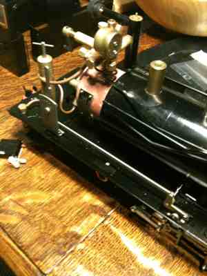
So to fit the r/c. First job is to see how to remove the body. Easy, four bolts, just like the Lawley and Caradoc. Oh no it's not. On the top of the right hand side tank is a cunning little bracket. Everything pulls off and then the bracket starts to bend.
The bolt head is hex and is 2 mm across the flats. Do I have a nut spinner this size? Certainly not. So a question is posed on here and the answer comes back to use a socket head bolt or a squashed brass tube. I discover that an M2.5 socket has a hex which is 2 mm across flats.
Update 3rd March 2010:
Ooerr missis it's all in bits...
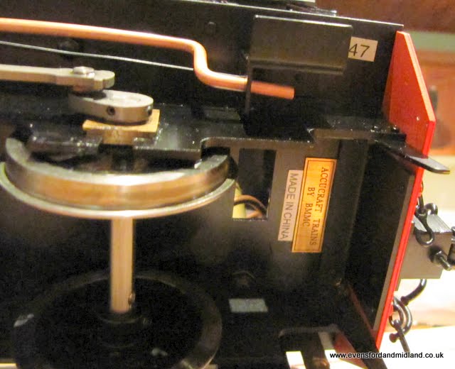
The reverser is rather unfortunately not drilled for the servo rod (unlike my other two Accucrafts). I understand from James (midwalestokie) that the ones which come r/c-fitted by Accucraft don't have the reversing lever. That' is not OK as far as I am concerned. On more than one occasion I have had flat batteries (who left the switch on then??) or also I had a servo go u/s. The reversing lever allowed me to run in manual, which is fine and even preferred by some souls I believe. So whilst I could have fitted the servo directly to the valve linkage, the CME insisted that the loco retained its lever to give the manual option in case of having to have the loco limp home. This meant stripping the lever off to be able to drill a hole in it just above the quadrant.
I should mention the jolly good fun to be had in removing the loco body. What a joy! The description in the recent Garden Rail article barely does it justice. "The tanks and cab were removed by loosening the bots under the running plate... etc." Oh yes, and the two in the bunker. And the two on the right hand side of the tank top which are M1.5 (mentioned above). Then bend the tanks outwards till you think they will take a permanent set (which they didn't thank goodness). Anyway it's off now and I don't reckon it will be off and on very often, unlike the Lawley and Caradoc, which are literally a 5 minute job even now with all the extra gubbins like servos and linkages on board.
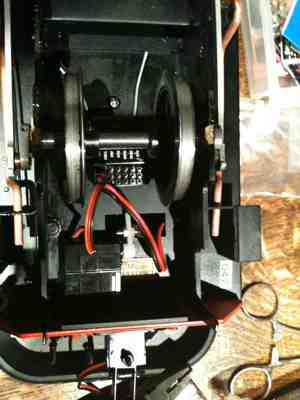
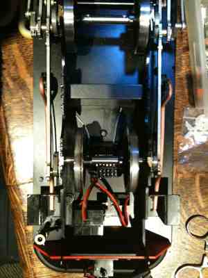
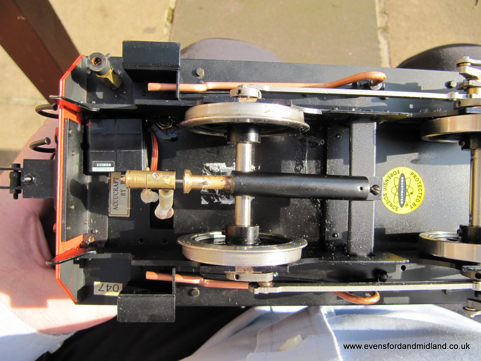
The tiny Spektrum AR6110 receiver is mounted underneath the chassis between the rear wheels and above the axle using servo tape (for the moment at least, further investigation will be undertaken). It will certainly need a cover to stop water and muck splashing up into it. Now the body is off, I might consider swapping the Rx for an AR6110E in which the EMR has recently invested. These have the connectors directly on the end rather than at right angles and one might fit in the side tank more appropriately. It would be drier but much warmer in there.
The picture shows the wheels in the 32mm position to make sure I can visit David and others.
Strangely, the other wheels are still at 45mm...
Plenty of pictures to help others. I always find it such a help to be able to see how others do this. It always feels like I'm inventing wheels and things when I fit r/c. So many variables, such as sizes of servos, servo and linkage mounting methods, battery types and positions, switch types and positions.
So the next step is to decide exactly where the servos will be mounted. The regulator servo is currently mounted with servo tape directly under the hole in the cab floor. I am using very thin metal gear servos which are intended to fit inside an aircraft wing. I have had one on the Lawley gas valve for a while and it has done many miles with no trouble. In my experience, it's great to be able to change the servos with minimum work because I have had two go u/s in the last year.
Update 5th March 2010
Having refitted and removed again the body, I now have a better idea where the servos will fit. The regulator servo is already mounted under the cab floor. The linkage will be a loop round the existing regulator lever. The reverser servo will be fixed inside the right hand cab with servo tape and will have a short rod. It will be visible inside the cab but only just. The gas valve servo will probably mount on the cab side too. Exact location still being decided. The whistle servo will mount on the cab floor. I haven't finally decided to fit a DJB whistle but it's heading in that direction.
Update 6th May 2010
The whistle has arrived (at Stoneleigh) and this had been the cause of the big delay. It mounts under the cab I was concerned about fitting it all in and about the waste steam flowing all around the receiver and servos. They are designed for aircraft, not steam engines. Electronics and water are not happy bedfellows. So I decided to relocate the receiver in the cab bunker. I must say I have been a bit stuck on this and still have not decided where to put the rest of the servos.
Update 27th May 2010
Decisions on the servos etc are now all behind us and the loco has entered service.
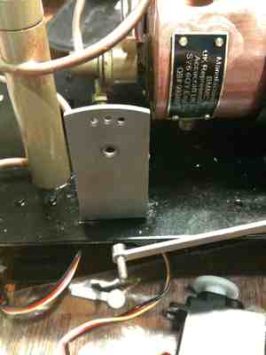
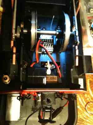
Here is teh plate for the reverser and whistle servo. The whistle valve is connected to the servo via a cable, which has teh major advantage that the whislte can also be operated manually without forcing the servo. This is especially useful when testing and setting up the whistle.
The receiver is now changed to an AR6110e, with the connectors on the end and the battery pack is a 5xAAA which is significantly smaller than the 4xAA pack. These therefore both fit snugly into the bunker and will allow a disguise of a coal load to be put over them.
The inside of the cab is now off-white too, which makes a big difference to the appearance IMHO.
Burner mesh
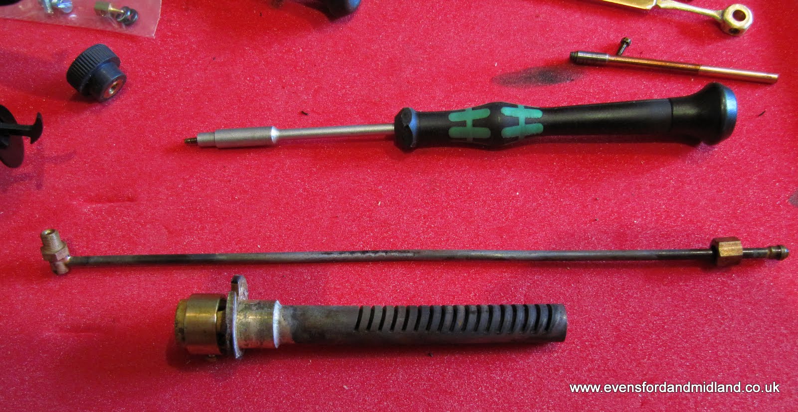
Great fun was to be had trying to work out how to extract the burner. The super-heater tube has to come out. On the Lawley, this is easily done by removing the smokebox and loosening the nut on the end of the super-heater tube but the Earl smokebox is more of a challenge. It didn't come off completely as it was one of those situations where you can imagine having the whole loco down to its individual component parts. It actually came off with the removal of two screws underneath, although it went back on more easily by loosening the front buffer beam.
The burner then came out in the same way as the Lawley by undoing the gas pipe from the valve, pulling out the gas jet and pipe assembly from the burner, undoing the cross-head screw from the burner and pulling out the super-heater tube enough of the way to allow the burner assembly to be jiggled around and removed.
This is what it looks like. The super-heater tube is above the burner in this picture. This is a standard design of Accucraft burner.
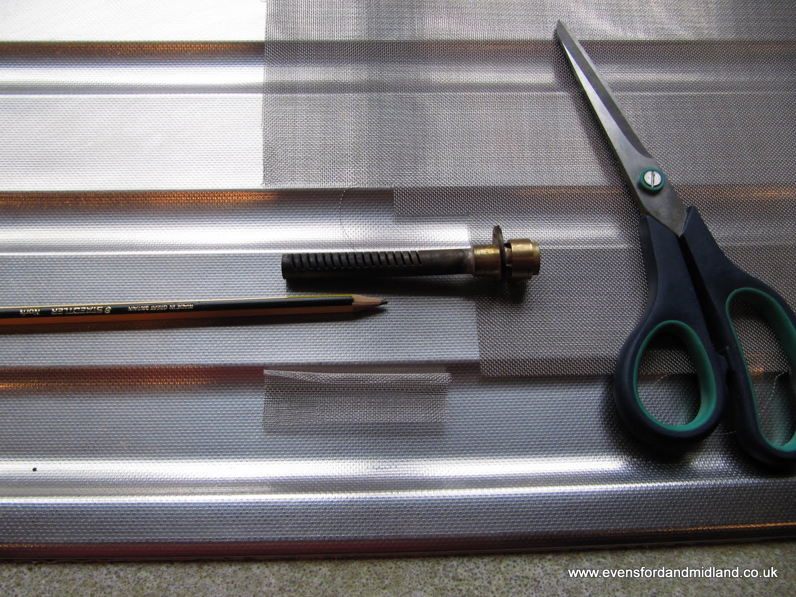
Here is the equipment and material needed to fit the mesh: 40 mesh stainless, scissors and a pencil or something of a smaller diameter than the burner. Roll the mesh round the pencil. I don't know who originated this idea but I learnt it from Tag Gorton.
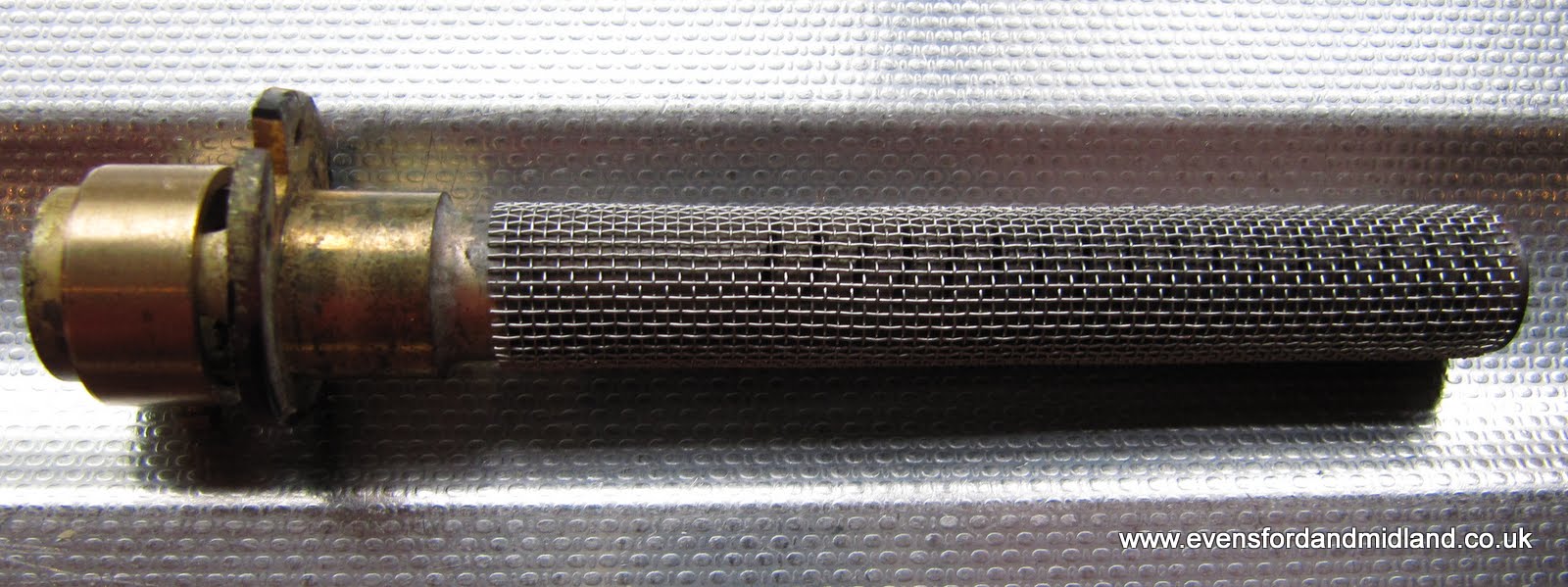
Here is the burner with the mesh fitted.
The burner fits back into this hole...
Update 27 May:
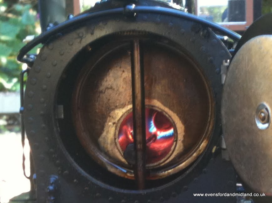
The burner mesh can be seen working in this shot through the smokebox door. The mesh is glowing and the burner flames can be seen to be in very small spikes instead of much bigger strips from the standard burner. The radiant heat is considered to be a "jolly good thing" in burner circles I believe.
Sorry for the slightly blurred piccie but other changes are now visible too. Much more of the metalwork is black, particularly the boiler and lubricator. The whistle valve and pipe down under (down under???) the floor can be seen too.
Ahhh now to force the decision on the exact location of all the rest of the r/c gear.
Whistle
The DJB whistle is fitted underneath the footplate. I must say it is very low down and I am a bit concerned about it but so far it has not caused any problems. A problem which did occur on the first full run with the whistle (at the Flatland Open day) was that the silicone pipe connecting the whistle to the copper pipe kept blowing off as soon as teh valve was applied. This was solved by putting a cable tie tightly round each end of the silicone pipe.
The pipe passes up through the hole in the footplate and connects with the soft copper pipe into the whistle valve on the right hand side of the cab.
Entering Service
The Earl entered service on 15 May 2010 on the Evensford and Midland Railway, hauling a goods train as the first turn.
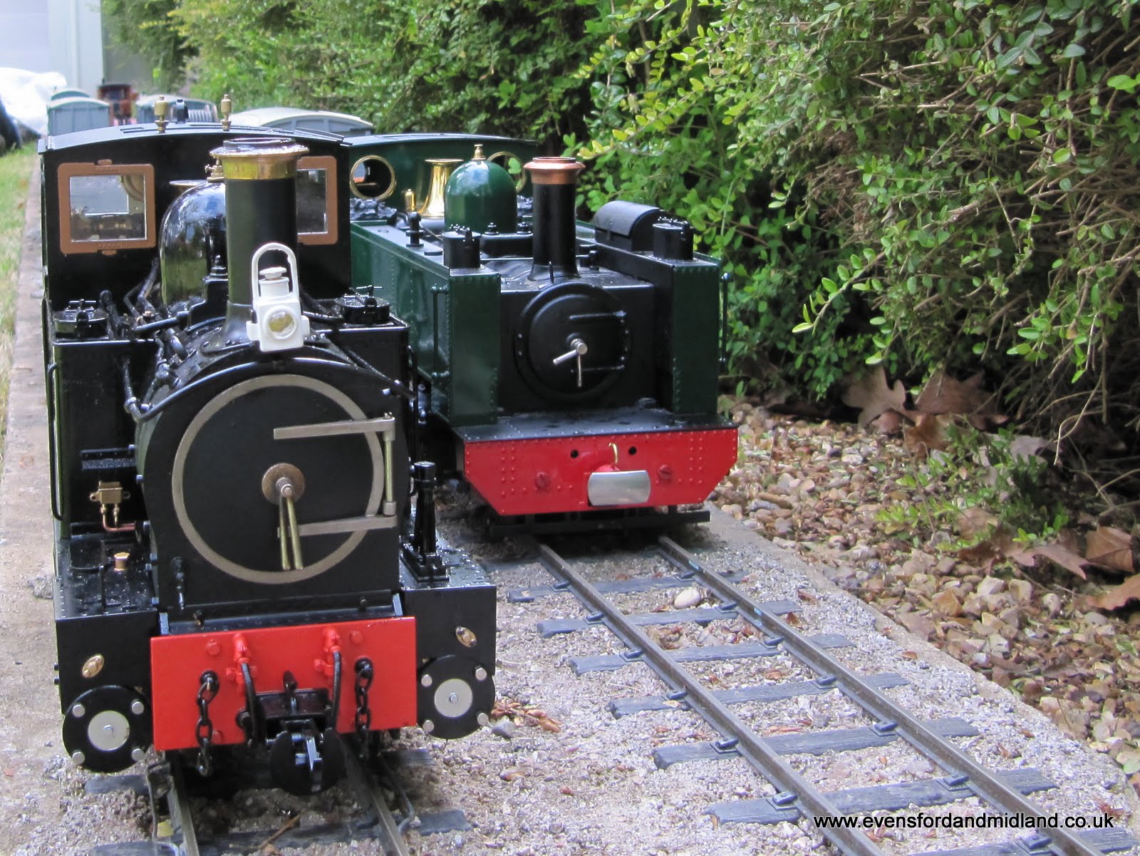
This was immediately followed by a visit to the Flatlands Washes Railway on 16 May. Here The Earl is seen next to GWR brother loco, Kevin's VoR.
Haulage capacity was put to the test and The Earl measured up well...