by Chris BirdIntroductionAs I start this article in July 2015, Garden Rail magazine is serialising the build of a 7/8ths inch scale Hunslet, based on the famous Jack. I am hosting information pages on the project on my www.summerlands-chuffer.co.uk website, but am writing it up here as I go along as it is much easier and quicker. If you have not seen the project before, then this loco is based on the Roundhouse 0-4-0 chassis and the Lady Anne type boiler. Although much of the rest could be scratch built, Brian has arranged the supply of laser cut parts, etched body and many castings, including the distinctive smokebox as a 3D print in steel! In my build, I shall be using many of the parts that are available (see my website for details). Please note that although the drawings are in the magazines (starting with Issue 251) there have been some corrections and these can be found on my website as well. And finally, I should say that I am not commercially involved in this project, other than to supply a special Chuffer for the completed model. The following is my simple account of what I did - it does not replace Brian's instructions (it should be read in conjunction with them) and there are, of course, many other ways to approach it. Hopefully though, my loco will look something like Brian's superb model below! And jumping forward in time - here is my Jack completed to the same stage as Brian's in the photos above (just click on the image to see it larger): And here it is with the lubricator pipework, whistle and the radio control installed.
And here is a fine model just completed (May 2016) by Dave Oliver who lives just a few miles from me. He sent me these photos - just click on them to see a larger image. Dave used the Brian Wilson smokebox, as I did, but has used the Modelearth castings and a Roundhouse lubricator with a bottom drain which frees up the cab doorway. At one point I had planned to make my version satin black and Dave has gone for this option. I think it looks absolutely superb!! Incidentally, Dave tells me that instead of using mounting blocks to fix the cab in position, he made two extra 'handrails' (8 BA threaded rod soldered into 3/32" tube) soldered into the front corners of the cab. This required two new holes in the footplate, but takes up no space in the cab as my blocks do.
The ChassisThe Roundhouse chassis is very nicely engineered, but the first job is to start modifying the side frames to take account of the lowered cab. And the first decisions are: 1. Am I going to relocate the dummy springs? YES 2. Am I going to relocate the reverser rod to the correct side (as this has implications for the drilling of the holes for the gas tank bracket)? YES - so the holes go in the left hand frame. The Springs I decided to mark and drill the holes in the springs while they were still attached to the frame as I just didn't fancy losing these fiddly bits of metal.
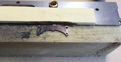
The first thing I did was to take a piece of 2"x2" softwood and cut it to length so that the frame 'clipped' on to it (you could screw it to a piece of wood). This gave a nice stable base for me to work with.
I blackened the metal with a Sharpie permanent marker so that the marks would show better (it comes of with meths or etanol). As you can see in the photo, I didn't continue the centre lines down on to the frame as Brian suggests - I forgot!! The lines are at 1.5mm from the edge of the hanger and the top one is 1.5mm down. I carefully marked the centre of the hole with an automatic centre punch.
A bench drill is really handy for drilling the holes accurately ...
....or nearly accurately in my case!
With the springs drilled, it was time to cut them off. I considered using a hacksaw, but then decide to use a Dremel cutting disc. With eye protection on and a piece of wood as a guide (steel would have been better) I cut them off - all but a little tag.
 This meant that it didn't fly off into the workshop - and I could detach them easily. Cutting the step for the cab
Now it was time to black the rest of the frame and mark it out for the part where the lowered cab will be. I use the digital calipers as a simple and effective marking gauge. I did consider using the cutting disc and even started the cut, but it was too thick and rather too many sparks for my liking, so I used a hacksaw. I cut to the waste side of the line (as my hacksawing is not very tidy) ... ...and then filed it to the line. Marking out and drilling
Now it was time to mark out all the other holes - including the ones for the gas tank as mine would be on the left hand side of the cab. And I soon realised that I should habve marked the spring hanger centre lines so that I could locate the position easily. It wasn't a real problem as I was able to measure from the other one. There are quite a lot of holes and so it pays to take plenty of time over it. Check and double check before drilling! Brian refers to many of the holes by their BA tapping or clearance - but to save you looking them up:
6BA Clear - 2.85mm
8BA Tapping - 1.8mm
8BA Clear - 2.25mm
The two holes at the rear of the frame and the lower one at the front need tapping 8BA and all of the holes need cleaning up on the back of the frame - I used a countersink bit. And so I have the first side of the frame ready - it took me about three hours (including taking the photos etc.) The second side frame didn't take so long - about an hour and a half. This time I did use a steel guide, held by magnets, while cutting off the springs - and I remembered to have the centre lines marked on the frame! I did, however, make a small mistake while hacksawing and went a bit far. I filled the sawcut with solder and filed and sanded it smooth. Buffer beams and cover plates
Some folk will cut these out from the plans and others will modify the Roundhouse beams as shown in the articles. I took the easy option and am using the laser cut steel parts from Model Engineers laser, here in the UK At this point I re-read the instructions and remembered that I should have purchased a rivet snap for the 1/16" rivets (sorry - this said 1/8" before which was incorrect). Plan B was to do what I usually do - use solder. The rivets would not go through the holes, but a quick run through with a 1/16" drill and they pushed in OK. I needed them to be a tight fit as otherwise the solder runs through and makes a mess. With them all in position, heads down on a flat surface, I just gave each stem a dab of flux and then used the blowtorch. When hot, just a touch of solder on each ran nicely. It was then a matter of snipping them off as flush as possible and filing/sanding the back flat. I would not recommend using the linisher (bench belt sander) to save time - as cleaning up the scratches when you slip takes ages ;-(
Eventually it was done
Please note that I have been given to alternative methods for fitting the rivets without the use of the correct rivet snap. Dave Oliver has used super glue (from behind) to good effect and Andrew Foster of GME Bridges in Ontario has told me that a carpenter's nail set (punch) works very well. He mounts one in a drill press and uses a flat anvil (piece of bar) behind. He has done many thousands of rivets on his bridges in this way. I have just bought a cheap set and it looks very promising.
At this point I looked at the drawings in the mag and realised that I had forgotten to drill for the coupling/buffers. The ones I am using are prototypes produced by Brian using a metal filled resin (3D printed I think. These will be available as a brass casting in due course. Now I quickly saw that these are going to be a snug fit between the beam mounting bolts (6BA small head), so I put these in position before marking. I used the Sharpie again. I marked through the holes with the buffer flush with the bottom of the beam. Spacers and trial fitting
The spacers are necessary to get the chassis up to the correct length. I used brass - about 6mm OD with a 3mm hole. In fact I already had some in my parts drawer and these just needed shortening by about 1mm. It is possible to use nuts instead, but please note that what you use will depend on what couplings you use (see below)
I was now able to trial fit the buffer beams, using the spacers, and find where little errors had crept in during my drilling. I fitted one Roundhouse frame spacer (using screws to be replaced by small head bolts) and needed open out the top holes in the front cover plates to clear the screws. Then I needed to adjust one bottom hole with a fine, round file so the the plate would sit square (fixed with 8BA small head bolts). At the back I needed to reduce the spacers by about 0.25mm. (Please scroll down a fair bit to see a different solution to the spacer issue)
It is important to think carefully before altering anything as you might be correcting a symptom instead of the cause!
In the end, all fitted nicely and sat square on a surface plate. The slight bend is due to my iPhone camera! One thing that I can now see is that the buffer beam spacers foul the top screw holes for the buffers. I think that I shall have to file a flat on the spacer and possibly also on the 10BA nut - we shall see.......
Assembling the chassis
After a night to sleep on it, I think that it would be best to test assemble the frames with about four Roundhouse frame spacers before trial fitting the buffer beam spacers and cover plates - that way you know that it is square!
I was able to modify the buffer beam spacers by holding them in pliers against the belt sander - crude, but it worked! Of course with the final brass casting (or any other coupling) this may not be necessary, but you can see below how it worked for mine. I must confess that it was a bit fiddly to re-fit the buffer beams. The bolt heads touch the coupling and so cannot be 'twirled' - and that means getting the nut on and tightening with a fine BA spanner. I was thinking that I would not want to do this many times as I stood back to admire it. But something was wrong - why were the main frame spacers at the bottom? Oh bother, I had bolted it on upside down! In my haste to rectify this, I dropped one of the new buffer beam spacers and spent a happy ten minutes searching for it........
A key decision in assembling the chassis is what fastenings to use. Brian recommends using small head BA bolts - these have a head one size smaller than the thread size. The slight difficulty, though, is that I couldn't find them in metric - and the frame spacer threads are 3mm. Brian assured me that the 6BA would go in just fine - and they do - though they get a bit stiff after a few turns. They look so much better than the cheese-head screws though that the slight engineering compromise is worth it. Compare the bolts with the screw below and make your decision!
Incidentally, that middle spacer with the screws will come out as there will be an SSP Slomo in there.
At this stage I began to think about painting the chassis, but before getting to that, I couldn't resist trying the footplates (from Model Engineers Laser) in position, together with the 3D printed smokebox :-) The dummy springs again (and important Slomo info)
And then I remembered the dummy springs! I'm not sure that I want to turn the dummy shackle pins so am trying 1/16" rivets for size - they look OK to me...... The springs are attached using 10BA small head bolts which are smaller than any nut spinner that I have. A small piece of slightly squashed 5/32" brass tube does the job though. Well.....after a couple of days to ponder, and a brief consultation with Brian, I decided that the rivets were a bit too big. In fact the article shows 1.6mm stubs, exactly the same diameter as the rivets - but Brian suggested turning down 10BA bolt heads, so I did.
But before that, there was another issue that was much more important. As I planned to fit an SSP Slomo, the front dummy springs would prevent it fitting far enough forward by 10.5mm. Brian explained that I needed to reduce the thickness of the spring to 0.9mm to allow enough room. Now this could be milled out or perhaps ground out with a Dremel, but as I don't have a mill - and it would be mighty fiddly - I decided to make a simple jig.
I marked out where the metal had to be removed..... ...and quickly decided that it would be easier to remove it for the whole length. I drilled a piece of steel to match the holes and then drilled through into a block of hardwood. This allowed me to mount the spring: I was then able to remove the metal with the belt sander and finish with a file. There is, of course, no room for a nut inside the frame for the rear leg. As the clearance hole for 10BA is the same as a tapping hole for 8BA, I tapped it. I then measured the thickness of the frame plus the leg and screwed a nut on to a small head 8BA bolt to give this length if cut off flush. After cutting I tidied it up with a fine file, unscrewed the nut and it fitted a treat. So it was back to those stubs. I turned the heads of the 10BA bolts to just remove the hex and then ran a 10BA tap through the holes in the spring. Once I had put them through I thought that it would be a shame to just trim them off, so I bent a piece of brass to represent the spring and soldered it to the bolts.
A small piece of brass from the scrap box was soldered in the centre and the whole thing cleaned up with a fine file and abrasive paper. Below you can see it in position on the left and on the right, a much simpler approach - just solder in the rivets and cut the heads off behind! And from the back, cut away to give the clearance for the Slomo.
I just have the other three springs to do now!
Right - they are now done - and the first one was the easiest. On reflection, if doing it again, I would slip fine brass tube over the 10BA threads and solder the spring to that - but then I don't plan to do it again! I checked the modified springs to see if I had the required 53mm clearance for the Slomo. I did - 53.1mm - phew :-)
The Right Hand Lifting Arm
In the Garden Rail article (252) Brian explains how to modify the Roundhouse lifting arm so that the reversing reach rod can be moved to the correct, right hand side of the cab.
The alternative is to buy one ready done from Brian - which I did! Back to the Buffers and buffer beam spacers
When I put the composite resin buffers on, Brian felt strongly that I really do need to have proper cast ones, so he sent me a pair - and they arrived yesterday. They are very nice castings, from the same master that Si Harris will be using at Modelearth, though these seem to be in nickel silver. The holes were in very nearly the right places and after running a drill through the castings, I only needed to ease the buffer beam holes a little with a fine needle file. Now other builders will not be changing their buffers but a quick safety warning. If you are opening up a hole with a needle file, put the work piece in a vice. If, as I did, you just-do-it-quickly-on-the bench, there is a good chance that you will stab yourself with the file. And it hurts - a lot!
Here is the new buffer in place:
Last week I had a phone call from neighbouring garden railway enthusiast Dave Oliver. He is collecting the parts for Jack, but on reading about the spacers, tipped me off about a simple solution. He suggested that rather than use a spacer, just using two 6BA nuts would be simpler. Lock the first on the bolt behind the beam and adjust a second nut to give the spacer. When this is in the correct position it can be secured with a little super glue. In practice, I found that two 6BA nuts, tight together, make about 5.5mm which is spot on for my chassis.
The inner nuts have to be in the correct position for the buffer nuts to fit, though smaller 10BA should not have a problem. And here just placed in position: And yes, I do need to finish cleaning up the buffer casting and drill the hole!
Paint and Colour SchemesRight, the fourth installment of Brian's series in Garden Rail magazine (253) has just landed, so it is time to catch up with the build. And it is time to make some decisions and do some painting. Now I do know that the thought of painting a loco strikes fear into the hearts of some folk, but it really isn't very difficult and is hugely rewarding. There are pitfalls and these are mostly to do with not doing one's homework - and there are simple techniques, which with a bit of practice just work! So please forgive me if I do a bit of preaching before reporting (experienced painters can skip this part!).
The decisions: 1. What type of paint? (yes, this is the first one - because it dictates what colours are available to you) 2. What colour scheme? 3. Where will it be painted? 4. How will it be painted? 5. What kit is needed. In Brian's article he kindly suggests reading my article "Painting Locos the Easy Way" here on the GRC (just look under Workshop or use the search facility. Have a read of this to put you in the mood if you have a few moments. The facts are the facts, but the method I use is just one approach - there are those who like to let paint 'mature' between coats etc.. It is up to you..... but here are some quick thoughts:
1. What type of paint? Well let us be clear that the widely available, acrylic car spray paint is NOT SUITABLE for boilers - it goes soft when heated. Matt black is OK and satin black used to be OK but recently, it too goes soft. These paints can be used on platework - and I have done so, but not on the boiler wrapper. And as this is a large part of the paint on Jack....well, I think you get the point! If, however, you can get the old Cellulose car sprays, then this is fine - and there are companies that will mix it for you in the colour of your choice. You have to be guaranteed that it is cellulose though. Or go for a high quality, authentic railway enamel such as supplied by Pheonix Precision Paints in the UK. It is slow to dry, but is superb. 2. What colour scheme? I asked Brian what he had used on the prototype for the article (and note that this is NOT the loco at the start of part 4 which is a loco he built for a customer). The answer was Midland Express Crimson for the boiler, cab, the outsides of the frames, cylinder covers etc., Midland Vermillion for the inside of the frames and buffer beams and black for the smokebox, footplates etc. 3. Where will it be painted? It needs to be warm - outside in the Summer is fine on a still day, but if inside, you must have the right equipment. 4. How will it be painted? Brushes really are no an option. Aerosols of the right paint can be tricky, so it is essential to practice. And the same goes for an airbrush - practice on a bean can with the label removed! 5. What kit...? If you are painting indoors, and especially if you are using a heater, then the correct mask for paint solvents is ESSENTIAL - not a dust mask or the one you have had for years! Good ventilation or a simple extraction system is important too. The rest is pretty simple - just a spray booth made from a cardboard box will do the job. You need wet and dry abrasive of various grades - some 600 and a little 800 and 1200 for dealing with the odd mistake, and you need a can of cellulose thinners for degreasing. Here is a spray booth I made later - I used my old, paint encrusted one for the first part of the painting.
My Paint SchemeOK we are back on my project now and after hearing from Brian about the colour scheme, I decided that I would do the same and that meant using enamel. I worked my way through the Pheonix website and filled out my order - then, at the last stage I must have typed a wrong number for my card as it deleted everything and too me back to the start. Oh Bother - I said and decided to try again the next day. But when the next day dawned, my brain had decided on a different path that perhaps few will follow. I thought about the complexity of a maroon chassis with vermillion inside and I thought about the fact that I am not that keen on vermillion buffer beams as they always seem a but 'orange'. I looked at the pictures of Harvey Watkins' Jacks which have black chassis (below right - the left hand one is a scratch built Jack that I used to own) - and I liked them.
So I decided on a black chassis - simple - the same inside and out. Now I had two high temperature black paints in stock. One, by Rustoleum, is for barbeques and the other by Baufix (Lidl's own) is for general use. I tried them and both gave a satin matt finish. I baked the Baufix at the 160 degrees Centigrade as recommended and it is superb. Then I thought, why not do the loco platework matt black too - with the same paint? And so the project became "BlackJack"! It is an industrial engine and there may well be some simple weathering on the brass etc.. And if I change my mind, I could get another boiler wrapper and cab and do them maroon! But what about the buffer beams? I was passing by Halfords, so I thought I would check out the high temperature reds - and they had one - a flat matt .........vermillion. Mmmmmm....... well I could give it a try - and vermillion really is what they used to use.....(please note that with the benefit of hindsight, I would not use this paint as it rubs off. Maybe a lot more coats than I gave it and perhaps a varnish over would help)
This just left the smokebox which really does need to contrast with the boiler I think. No problem - a stove paint called Hot Spot is a dead flat, almost grey finish that I have used before. A quick order from an Ebay supplier and the die was cast. Preparation
When I did the final assembly on the chassis, I made sure to ket the surfaces of the spacers with 600grade abrasive and I did the same for all the steel chassis parts. I made sure that all was tightened correctly and then degreased three times using kitchen towel and cellulose thinners. I used my old spray booth (box) and did not disturb the layer of paint dust (either leave it or totally de-dust it with a vacuum).
With the booth set up outside, I put the chassis (without the buffer beams) on a block of wood and gave it all a thin coat of etch primer (Upol Acid Etch 8). Now I know that some high temperature paints say apply to bare metal, but I ALWAYS use a very thin coat of etch primer). You will see that I put a little blue tac in the axle bearings.
I then removed the blue tac and whn the primer was touch dry, I baked it in the domestic oven at 100 degrees C for 20 minutes. When just warm it was ready for the top coats. Here the first one has gone on and then the chassis inverted when it was touch dry. I use a 2Kw fan heater to speed this up. I gave it all three good coats, drying it in between using the fan heater. It was then baked at 160 degrees C (as per the instructions) for an hour (note that with most paints 80 - 100 C is enough). Now those who have read Brian Wilson's Part 4 might wonder why I am not following his idea to paint the buffer beams in situ. Well my only excuse is that his design makes it so easy to remove them that - well - why wouldn't you?! I have to admit that I would normally paint the buffer beams and buffers separately, but when I thought about it, I realised that (after all the hassle of fitting them) I would never remove them. So I decided to spray them as-one. The black was the easy bit - just prepare and spray the backs - not forgetting the spacers. These all had a bake at 160 C.
Then it was a matter of masking to spray the fronts. It would have been simple if I had removed the buffers - but that decision had been made! I used Tamiya masking tape (below right) to deal with all the edges. This is expensive, but gives a fine cover if one goes over the edge with a finger nail to ensure it has stuck. I was, perhaps, being over cautious, using Tamiya tape - followed by standard tape - but I wanted to get it just right. You can see below that the back had over-sprayed round to the front of the beams.
Then it was a few coats of the vermillon HT paint. This dried almost instantly to give an absolutely flat matt. I did remember that the fly cranks and screws also needed to be this colour, so they were rubbed down, de-greased, etch primed and sprayed. After removing the masking from the buffer beams (which was about 99% successful) the parts were given a 160 degree C bake in the oven and then I was ready for the assembly.
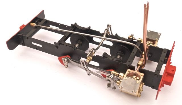
Assembling the ChassisThe chassis is, mechanically, pretty much a straightforward Roundhouse kit and at this point I have to say that it is superb and mostly (say 99%) a joy to build. The instructions are very clear and it goes together very well. Hundreds (and probably thousands) have been built by first timers, but I thought that I would record the sequence here for those who still think it is beyond their skills..... First the buffer beams went back on, using the spacers at one end and the two nut method at the other. Then it was a matter of preparing the fly cranks. Now these are a VERY tight fit if you try to force them on to the axles, so it is necessary to ease them a bit with a fine flat file. I run this along the edges of the square part of the axle first to make sure there are no burrs and then I file through the square hole in the fly crank, first to remove the paint (yes you could mask the holes with a little Blue Tac) and then just lightly remove a little metal from each face of the hole until it just pushed on to the square axle end snugly. It is worth taking time to do this as they are then easy to remove for fitting a Slomo sprocket. I ran a 1/4" reamer (though a 1/4" drill would be fine) through the bearings and through the wheels (with grub screws loosened) to ensure an easy fit. Then it was simple to assemble. Now when I looked at it, I was delighted with the satin black and the vermillion was definitely growing on me, but those chrome wheels.....er..... no.......
So it came apart again. I needed to abrade the wheels to key the shiny surface and so mounted them on a 1/4" drill in the battery drill. With this spinning at full speed I applied one of those fine foam sanding blocks to both sides. They were then degreased with thinners and placed on a block of wood. At the same time, I thought I would spray the cylinder covers and so prepared these as well Ready for spraying - I glued a little batten to hold the covers
I etch primed with Upol Acid etch 8 and after drying and turning the wheels over, they were ready for baking. Then they were sprayed with the High Temperature black. This time for the baking, I didn't want the wheels to touch anything and so rigged up a bent wire to hold them. I will admit that the Mark 1 version of this had two legs - and no possible way of getting the wheels on! Next came the coupling rods - and these needed to be eased with a fine needle file to make them slightly oval. When both fitted, they need to rotate smoothly with no tight spots. This takes time and it is essential to take it steady, rather than take a lot off at once.
The eagle eyed will notice that one frame spacer is missing. This is because it is not needed when fitting the essential (to me) Slomo.
Building the MotionAlthough this looks a bit complicated, it really is very simple. It is essential to read the instructions - which is obvious for the beginner, but also pretty important for those with a bit of knowledge. It will save having to do things twice! Also Roundhouse are very thoughtful in providing spare screws and washers - you may well need them........ The next step is to fit the cylinders here shown with the slide valves.
It is necessary to bend the soft copper pipes and it was here that I got a bit obsessed with neatness. I had determined that the chimney on jack was directly in line with the exhaust exit from the cylinders and decided to do the bend and fit the cylinders in a spare five minutes. I found a brass rod of the right radius (dowel would do) and put the neatest 90 degree bend in the pipe before fitting them. It was while I was admiring them that I wondered how the superheater T fitted - and so, belatedly read the instructions. These say "the exhaust pipe(s) should be bent forward and slightly up, out of the way". Doh! Luckily it was easy to put right (though not so neat!).
I then fitted the valve chests and slide valves as per the instructions. It is really important to ensure that the D shaped nut is correctly seated in the slide valve (see later!).
To fit the superheater (from the boiler kit) I slid a gland nut, followed by an O ring on to each inlet stub and then slid the T into place. O could then do up the gland nuts - - not too tight.
I decided to bend the superheater at this stage and, having the smokebox and boiler to hand, I was able to place them in position and see where the bend needed to be. In fact the boiler comes quite far forward and so I aimed for a vertical rise and then a smooth curve (round a dowel again) to run along the centre line of the boiler flue. In the Boiler Instructions it says that it should end up about 10mm above the chassis and parallel to it. I found that it needed to be 18mm above the chassis. It is quite difficult to bend, even over a dowel, and it is important not to strain the copper steam pipes when applying force. It sounds worse than it is , though, and a few minutes sees it done.
Next come the connecting rods (remember the washers) and at this point I fitted the dummy combination lever set. It needed a tiny amount of fettling with a fine needle file and then I just loosely fitted it in position with the valve screws, just to keep it out of the way.
The return cranks went on easily and were roughly positioned (remember the washers again). I also fitted the 'penguins' and trial fitted the Weigh Shaft and Expansion Links
I then finished for the day and pondered about those shiny 'penguins' bearing bolts and weigh shaft.........
The following day I decided that the penguins and weigh shaft centre had to be black, so they were removed and painted in the usual way. For the brass bushes I used a brass blackening solution. I used Blacken-it, but Carr's Brass black is just as good. The parts were cleaned, degreased carefully and allowed to soak in the solution for a few minutes. Then removed and rinsed thoroughly. Here you can see the comparison: So I then put it back together, checked for free movement and came to fit the 'starlock' washers that retain the expansion link pivots. Oh joy! Now I do not know why they are called 'star-lock' washers because stars are at least visible some of the time (on a clear night). These little, lightweight beasts can instantly achieve escape velocity when gripped with the recommended long nosed pliers - and are then totally invisible!! After a number of attempts, the spare was gone and I was down to two. The first action was to move into the kitchen where the hard, light coloured floor would at least give me a chance of finding one. I then decided to forget the long nosed pliers and use a tube. I ysed 5/32" K&S tube but a dowel with an 1/8"hole drilled in the end would do - or even a thin bamboo. A piece of timber was placed against the expansion link and I held this in place with my elbow. The starlock was held in place by the tube which was then given a sharp tap with a hammer. As it went on, the shaft was rotated so that it went evenly. Hopefully the photo explains it..... All sorted and I think that the penguins and bushes look better in black... So then it was a matter of fitting the eccentric rods to the return cranks (remember the washer!) And finally the lifting arms and radius rods. Note that I have used Brian Wilson's right hand lifting arm rather than the standard Roundhouse, left hand one. This is because the original Jack had it on the right.
It was time to set the timing - and by following the instructions it was very easy. The return cranks must be in the right position, but then it is a matter of getting the valve travel right in both directions. By fitting the Roundhouse supplied Quicklink reversing rod, it is possible to clamp this in position the the chassis with a plastic spring clamp.
When I had got it as close as I could, I put a few drops of motor oil in each valve chest and replaced the covers - only to find that one of the D nuts in one slide valve had tipped enough to lock it solid. Off came the cover again and it was quickly sorted.
At this stage, I did not want to put a lot of oil on the moving parts so I just wanted a quick test on air. I put it in gear (held with the clamp) and used my compressor with the tyre inflation fitting. This clipped on to the end of the superheater pipe and a quick puff of air showed that all was well. It ran for a few seconds in forward and reverse.
Now it is worth noting that when Jack is assembled, it is not possible to remove the cylinder covers for timing adjustments without removing the smokebox (the overhangs prevent access to the inner screws). To check the timing properly on air and steam, you ideally need to be able to hear the beats - and that means fitting a Chuffer! This can be used either with the proper smokebox and chimney, or with just a piece of metal tube over it to give some resonance.
Fitting the Summerlands Chuffer
First I needed to trial fit the front footplate. (For cutting this from steel - there will be a fully dimensioned drawing on my website). I used the laser cut part and drilled the fitting holes 6BA clear and countersunk the rear two which end up under the smokebox. I haven't got the right countersunk scres yet, but had a couple that fitted for this stage.
The correct Summerlands Chuffer is the SCGP11 and to fit it in the correct position, you need the smokebox and chimney. As this is dealt with in a future installment of the article, you could somply cut 10mm from the top of each exhaust, fit the Chuffer and drop a piece of 1/2" tube ober it. It will make plenty of sound!!
As I do have the smokebox, this is what I did. With the smokebox reversed and sitting on the front of the footplate, I measured down 93mm and marked them with felt tip pen. I then cut the pipes with a cutting disc on a Dremel - but a junior hacksaw would do - just support the pipes well when cutting.
After cleaning up the ends of the pipes with a fine file, the Chuffer can be pushed on and tapped with a screwdriver handle to seat it firmly. Please note that the Chuffer shown here is fitted with the optional FX Control.
When assembled the chassis, I did think about painting, or blacking the cylinder ends - but decided that I didn't want the hassle. The issue with brass black is that I have found that the item needs to be immersed to get a good result, and although I could stand the front cover in a shallow tray of the solution, I could see no easy way to do the rear cover without removing it. As for paint, I like to abrade before de-greasing and spraying, and decided that .....I liked the shiny brass.
So what happened next? Well my fellow contributors on here wouldn't let me get away with it! I asked Brian what he does and he said, degrease, etch prime and spray with high temperature paint. Oh yes - and then touch up the missed parts with a brush......... So it looked (and still looks!) like the brass is fresh enough not to need abrading.
So off they came and I gave them a thorough degrease in a small bath of cellulose thinners. I mounted them in holes in a block of wood. A biggeer block would have been bore stable, and indeed essential if you still have the long exhausts. brian had also mentioned masking, so I did.
These were then etch primed with Upol Acid Etch 8. I took great care to ensure good coverage - no touching up for me! The had twenty minutes in the oven at 100 degrees C and then, when just warm, we ready for the same HT paint used on the chassis. I removed the masking tape ready for baking for 30 minutes at 160 degrees C. So then I was able to turn them over for a photo - and found that I had missed some parts after all - so out came the brush and back in the oven for a bit more at 160. Just after taking this photo, the card they wer balanced on slid gracefully to the concrete floor - so out came the brush again and back in the oven. At least I know they are not 'half baked' ! Re-fitting is a bit fiddley with all the valve gear assembled, but just needs a little patience (now where can I get some of that in a hurry.....). And with the Roundhouse cylinder covers clipped into place - i am pleased with the result (though I still like the shiny brass too!).:
The FootplatesRight - it was time to paint the laser cut footplates from Model Engineers Laser. First, though, because I had ordered mine very early on, I had to modify the cab footplate. This is because an error crept into the drawing supplied by Brian and the slot for the burner bracket was incorrect. The solution was very simple and took just a few minutes to do. Brian's full instructions are on my www.summerlands-chuffer.co.uk website and his photos show what is needed.
The burner bracket slot has to be widened by drilling, a couple of hacksaw cuts and then filed to shape. I found that by mounting the plate in the vice, I could do one cut with a junior hacksaw and it was easy to file to the line, which was flush with the vice jaw. Incidentally, if you are cutting the footplates out from steel, there are some details and a corrected drawing of the front footplate on my website in the Jack section. Here it is modified, and the mounting holes have been opened up to clear 6BA. This footplate can be used either way up, depending on which side you have decided to put the gas tank and reverser. The front footplate needs the centre front mounting hole opening up to clear 6BA - though I made it a little bigger to give some fiddle room. The two rear ones are opened up and countersunk to take the fixing screws which are under the smokebox and must be flush. If you hold the plate (rather than clamp it) under the countersink drill, you get 'frilly' holes. So clamp it! At this stage I cleaned up the water filler and made it a push fit in the other front hole. In fact I mounted it in the lathe chuck and carefull cleaned up the surface with a fine needle file and abrasive. Mine is a 3D print from Brian and could probably have benefited from a little more work! Then it was a case of mounting the parts on a piece of wood and priming - I used etch primer again. Note that the filler is separate and there is a 6BA small head bolt for the front footplate. This was baked and then sprayed with the HT matt black. Make absolutely sure that the edges get the full coats by rotating the work in the spray booth. Then, when touch dry, it can be arrange on a few nuts to lift it off the wood. Make sure the underside is down for this as there will be some sticking (You could use pins tapped into the wood to stand the pars on). Thinking about sticking, for the final coat, I fitted the water filler so that it would be bonded by the paint.
When the parts came out and cooled, I found, to my great joy, that I had missed one edge of the rear footplate. So that had to be sprayed - and I made the foolish mistake of putting it back in the oven top side down on the nuts. So it stuck - and I had to re-spray the top!
Eventually it was done - and I also remembered those two little frame extensions that come with the etches (but are not in GR until next month). Now this is jumping ahead a bit as the plans for the smokebox are in next month's Garden Rail magazine, but I know that some readers have ordered the 3D printed version from Brian, so I will bring this article up to date with mine.
The first thing that a builder will notice is that the smokebox can't be fitted with the superheater in place. This is simple to deal with - it just needs a couple of hacksaw cuts or the careful use of a cutting disc. With the front footplate in place on the chassis, the smokebox frame extensions can be test fitted and the smokebox marked for drilling and tapping 8BA (this may already be done on later ones, but if not it is simple and easy to drill. The picture below explains it: And here you can see how they fit on: There are two holes in each extension piece. The front one needs to be drilled to clear the 8BA fixing bolt and I drilled and tapped the rear one for an 8BA small head bolt. This I snipped off behind and filed it flat before abrading, priming and painting.
You can see from the photo above that the 3D Print surface is quite rough and needs a little work with abrasive paper and perhaps fine files. In fact it looks like well used cast iron or rusty platework, so the roughness adds character, but in places the print lines are visible so it is worth the effort.
I worked on mine and the de-greased and etch primed it. When it came out of the oven, I could immediately see that it needed a little more work on the 'shoulders'. I used 400 grade wet and dry and here in this not-very-good photo you can see it ready for a second thin coat. At this stage the chimney, which is a firm, push fit in the flare is not pushed fully home. When I was satisfied with the finish, then sprayed with Hot Spot - a stove paint that I know gives a dead flat matt finish. While the first coat was still wet, I just tapped the chimney home so that the baking paint would secure it. While dealing with the smokebox painting, I also cleaned up the smokebox door and etched then painted that with the same paint. Both had 30 minutes in the oven at 160 degrees C. It would be interesting to know how many of us are working on this Jack project. You can email me on summerlandschuffer (at) btinternet.com if you have questions or tips - or just to let me know!So, with the front footplate screwed in and the smokebox and rear footplate balanced on, this is what he looks like (click on the image to see it much larger): Here you can see the modified rear footplate in position and the slot for the Roundhouse gas tank bracket. And here you can see the position of the Summerlands Chuffer adapter which must be well clear of the bottom of the chimney: Smokebox CastingsThe latest edition of Garden Rail is out and focuses on scratch building the smokebox. Now about a year ago Brian kindly let me see the copy for this and...well....I thought that I might have a problem....or two....! Since then, Brian sorted it for the likes of me by first producing a 3D print for the smokebox, and now, with the benefit of a little more development time, a superb cast/ready built version (see my website for details www.summerlands-chuffer.co.uk). So as this months project is already done and painted (and next months too) I agreed with Brian that I would press on with the build. Now I need to say that some of the "castings" I am using (and some of the other parts) are ones that Brian has supplied to me direct (and some are prints) - but they are basically similar to the ones from Modelearth and so the approach will be similar. The wonderful smokebox was looking a bit bare in the last photo so it was time to tackle the Roscoe lubricators and the blower elbow. Also the smokebox dart was not right (though rather nice!) in shiny brass.
The lubricator castings (or prints in my case) need a bit of cleaning up with a fine file and then the brackets need to be black to match the smokebox. Here are the ones I used: (with the benefit of hindsight, it is necessary to decide what pipework or wire you are going to use and to drill the castings to suit. Mark it carefully, hold it firmly and use a sharp drill)
After cleaning up and a thorough degreasing with thinners, they were masked and etch primed. After spraying, the masking was removed and they were given 15 minutes at 100 decrees C in the oven.
Then they were masked again
And sprayed with the same paint as the smokebox: Hot Spot stove paint. When baked in the oven they matched the paint well and were bolted on. It was a bit fiddly but a selection of different spanners helped.
In these photos you can also see the blower elbow casting. As I wanted this to have a slightly used look, I cleaned and degreased it and then dipped it in 'brass black' (Blacken It).
Needless to say, I was rather pleased with the overall result! Another casting is the clack valve (water feed) that goes on the side of the boiler and is held by a screw through the boiler cladding. I dipped the base of this in the brass black solution to give it a slightly aged look.
The boiler
The Roundhouse Lady Anne boiler, does not really need painting, but I wanted the backhead in the cab to be black, and also there is a sliver of it visible next to the 3D print smokebox what needed to be black. So if I was doing both ends, I decided that I might as well do the lot. Which brought me to an important (and, I admit, rather scary decision). On Brian's loco, the pressure gauge is on the right, rather than on the left as standard. I asked him if he really intended us to bend that fragile little pipe over to the other side (he has to be kidding!). Well, yes, he said. Be firm and confident he said. Oh yes.......... Well I did it. I removed the pressure gauge (it is essential to do this as no force must be applied either to the gauge or to the thin connecting pipe) and bent the pipe to the right and then twisted it through 180 degrees. The copper is annealed and soft - though it was work hardened by the time I had finished. It would be possible to re-anneal the pipe with a small blowtorch if it hardens before you have finished. Get the part you want to bend to red heat (not the part near the boiler) and either allow to cool or quench with water. You can see the result of my efforts here:
It was really easy - and if it hardens up too soon, it is possible to re-anneal it by heating just the pipe to red heat and letting it cool. I then runned the boiler down with fine abrasive and degreased it. I used bluetac in the holes and a little masking tape on the threads. Here it is ready for etch primeing: And after removing the Bluetac, it was baked at 100 degrees C. With the Bluetac back it it was sprayed with the high temperature satin black paint and baked at 160 degrees C.: As mentioned above, the clack valve needs to be located and screwed through the cladding, as does the sand box. The question was where? By looking at the photos, I was pretty clear that the clack valve is on the centre line of the dome and half way down the boiler (left hand side). The sand box appears to be half way between the front edge of the dome flare and the smokebox. I will not tell you how long it took me to find these locations, but lets just dat it involved a spirit level, a flat plate and an engineers square (and quite a lot of muttering!).
I managed to mark them in the end (I will share this) and then centre popped and drilled. The issue now as how to countersink the holes on the inside (the castings I have are secured with countersunk screws). For the sand dome hole I anaged to spring the wrapper apart, but for the clack valve hole, I had to use my fingers to turn the countersink bit: The wrapper was then rubbed down with a 3M fleece to key it, followed by a thorough degreasing with thinners. I etch primed the wrapper in the usual way, but then I came to the crucial decision...the top coat..... ColourI explained earlier in the article that I had planned on the proper Jack crimson but then, bu chance, had decided on black. Well, when it came to doing the deed, I changed my mind again. I have read that often the real narrow guage railways used what paint was available at the local shop - and in a round about way that is what I did.... A couple of weeks ago, I was thinking about a simple test to see if paint was suitable for use on boilers (and wrappers) where the temperatures reach around 150 degrees C. I spotted a can of metal protection paint that I had purchased some time back from Aldi (a German discount chain that stocks all manner of stuff as special offers). I sprayed a tin can with this paint, which is rather slow to dry. Once touch dry, I baked it in the oven at 100 degrees for a while and then gave it another 20 minutes at 140 degrees. I then let it cool and checked it was hard dry. Back in the oven at 180 degrees and checked the surface had reached at least 160 before I took hold of it with folded kitchen towel. It it had failed, the towel would have stuck (try it with acrylic car spray!). This passed with flying colours and gave an incredibly hard finish. And what colour was it? A deep, glossy Brunswick green - a bit like the Victorian Great Western Railway colour. It was this that I decided to use and my thoughts of a grubby, weathered, black loco went out of the window! Here it is - and it smells very like Plasi-kote Project Paint (though I have not tested that). As I mentioned, this is slow to dry - like an enamel rather than a car spray. It says allow 5 minutes between coats, but I think ten minutes in a warm place is better. The slow drying makes it a bit vulnerable to dust as I found out by using my trusty fan heater! I gave the boiler wrapper three good coats, and when the final one was just touch dry, I baked it in the oven. I gave it 20 minutes at 80 degrees, then 20 at 120, then 20 at 140 degrees. When cool, the paint was hard dry, but there were some dust specs. I though about rubbing down and giving another coat, but there was plenty on there so I rubbed it carefully down with very well worn 1200 grade wet and dry (2000 grade would have been better). I then I polished it using an automotive cutting liquid (T Cut in the UK). After a fair bit of work with a soft cloth, I got a reasonable satisfactory finish. Here is the wrapper back on the loco still in need of a little more cutting in (click on the image to see it large):
The Sand BoxThe sand box that I used is the one supplied by Brian Wilson. It has nice detail and fits snugly on a boss, screwed through the boiler wrapper. In fact if fits very snugly - so the first job was to clean up the inside of the casting with a fine, half round file. This was also used to fettle the bottom so that it sat correctly on the boiler wrapper. The screw supplied was much too long so this was shortened. Then it was a matter of clening up the casting with fine filed and abrasive paper to give a smooth finish. As is often the case with casting, there was some loss of detail in one place, but that is invisible now it is painted. Rather than mount the box on a piece of wood and spray in the booth (cardboard box) I wanted to be able to get paint at a number of angles to get good coverage. I slightly tapered a piece of batten (a plant label) and pushed this up inside, blocking the openings with BlueTac as I didn't want paint inside. Now I could de-grease thoroughly with thinners.
Looking at Brian's locos I could see that he left the sand pipe collars as brass, but my attempts to mask them with fine Tamiya masking tape failed. In the end I used a small ball of BlueTac, flattened on one side and pushed on to the ends. I sprayed it outside on a warm day and was able to turn the piece through all angles. I then removed the BlueTac and baked it in the oven on a piece of wood. When cool, it went back on the stick, the BlueTac was replaces and I gave it two good coats of the green. Here it is after the first coat.
Then it went through the baking sequence (without the fan heater and therefore no dust) and it is interesting that one small pin-hole in the paint completely disappeared in the process. As an aside - if you bake at 140 degrees on a piece of resinous pine, the kitchen smells like a pine forest ;-) So here it is on the loco: Fixing the FootplatesRight - well the ladest installment in Garden Rail magazine is out and covers the model engineering side, rather than the buy the parts and fit it all together side - so I will get on with the straightforward (or at least relatively straightforward) stuff! After the usual tidying of the workbench I made some progress on fixing the footplates. The front one had the two rear fixing holes countersunk and, as I had not done this quite enough for them to be flush, I filed the screw heads a bit more so that they were flush where the smokebox fits. Now a few weeks ago, Dave Oliver phoned to tell me he had an alternative way and that was to drill the holes in the spacer to clear 6BA and then to tap the holes in the footplate 6BA. Thus he screwed through the spacer into the footplate.
I used two blackened screws for the front of the rear footplate and a small head bolt and nut through the centre hole. Here you can see the four screws in position: A Note on the InstructionsIt goes without saying that we should all study the instructions before starting (oh yes!) but on reading them this morning, I spotted the boiler and gas tank certificates lurking in the back of the instruction book. It is essential to keep these!
The Boiler BandsAnd it is important to read the list of parts you need to purchase on my website (or in the magazine) to make sure you have everything. My excuse is that when I ordered, the list wasn't there so somehow I only ordered one extra boiler band, instead of three. You get one with the Lady Anne boiler kit and you need three more. The penny dropped with me when I came to fit them - but for the rear one in the cab, I decided to make one from slightly wider strip.
For the front band I used a Roundhouse one and first cleaned up the edge with a fine file and abrasive to remove the tabs where they had been part of an etch sheet. I then polished the outside and bent the ends at right angles. By this time I had lost the screw and nut, but luckily I have stock! I bent it roughly to shape round a former (wood in my case but a suitable can would do) and fitted it round the wrapper. Now on the £D printed smokebox, the boiler wrapper and band butt up against the rivet heads and I found that I needed to file a bit from the end of the band to make it sit flush. I also found that the boiler tube fouled the superheater tube s, but I will come back to that. The second boiler band was the same as the first - so no problem. I made the rear band from strip brass to match the others for length and drilled the holes for 2mm set screws. I decided that this would be brass 'blacked' using Blacken It. As I needed a long shallow tray, I used some acrylic packaging tipped to make a V. I cleaned and degreased the brass and then just immersed it until it was about the right colour.
The finish is a bit fragile to start with, but it looks OK now. This band is used to secure the burner/boiler mount and one needs to overcome the desire to be tidy and mount the band off centre so that the mount can be centred properly. Mounting the BoilerI mentioned above that the superheater pipe was fouling the boiler. This is because the boiler goes a long way into the smokebox which is much shorter, front to back, than the Roundhouse one. Therefore the superheater needs to rise vertically rather that slope back below the bend. It was easy to adjust by putting a round bar (actually a large automatic centre punch) across the frame and bending the pipe round this. I also made a slight adjustment so that it went along the left hand side of the flue tube as per the instructions. With the smokebox screwed in position on the front footplate, the boiler can be threaded on to the superheater pipe and pushed fully home. What you will then see is that a spacer is needed below the rear mount - and the one supplied by Roundhouse, is, of course, too thin. I puzzled over this for a while, but eventually used a dial gauge on a flat surface to estimate how much was needed. At the second attempt, I found that 3mm was just about spot on so that might be a good place to start. I had a piece of 3mm scrap, but it could be built up from thinner sheet or filed down. Rather than have one end at an angle (that's what that odd bit of brass in the kit is!), I made mine rectangular - something I might live to regret ;-) When I had made the spacer, I blackened. When I cane to fit it though, I found the the hole was a few mm forward of the drilled hole. I have no idea whay, but I just drilled a hole in front and filed a slot. I
I used a long 6BA screw and washer to secure it from below. I then needed to tweek the superheater a little to allow me to fit the burner, which was sprayed with heat resistant paint earlier. And here you can see it with three of the four boiler bands fitted: The RegulatorThe sharp eyed will see that I have fitted the regulator (this is the standard manual one, but I would recommend the r/c one if you are fitting radio control with a Slomo). This was cleaned up with fine wire wool, degreased and blackened. The fibre washer was exactly right and it tightened into place as per the instructions - my lucky day! This is, of course, the manual regulator which is not ideal for radio control, but it will do for now. The Gas TankBrian has recommended to me that I bend the gas pipe to the format shown in the photos of the completed Jack. I am not yet totally convinced as it might be OK where it is if it had a long handle on it - though that would limit movement to not much over a quarter of a turn. We shall see......but in the meantime, here it is, balanced in position. OK - it was decision time! As you will see from Brian's photos, he bent the pipe with the valve forward and twisted it to bring the valve to the rear of the gas tank. I decided to go for the minimum bend option. This involved bending it back (towards the rear) and in a bit. There is no right or wrong way - this is what I did - very carefully! Hopefully this photo will make it clear: The paint began to flake where the bends occurred, but this is easily touched up.
The next job was to fix the gas tank in position. As su=ggested by Brian, I needed a spacer to bring the gas tank inboard a little to give room for the cab. I used some 0.8mm brass and when cut to size I marked and drilled the two holes. When I offered it up, there was a slight lean and the tank touched the boiler cladding (instruction readers will know that this is a bad thing!). A slight bend of the tank bracket made the bend square - if you know what I mean. Of course the small 2mm fixing screws and bolts had disappeared so i selected two from stock and used Blutack on a rod to hold the nuts in position to locate them. Screws are better than bolts as they are very near the footplate. I then set it up to take a photo inside the frames and spotted that I had picked up two different sized screws...... And so had to do that one again! So now it looked like this from above: The Pipes!I reckon that bending the pipes is one of those jobs is one of those tasks that seems scary, but isn't really. A bit like drilling the return cranks.......no....wait a minute....that is scary! The pipes are easy to bend, and if you get it wrong you can re-anneal them and do it again.
Now what follows only applies if you have opted for the right hand reversing rod and left hand gas tank.
Because the positioning is different from Lady Anne (shown in the instructions) this took some thought. I wanted to use the pipes as supplied for simplicity, though I could have made new ones to make the gas pipe more discrete. So I stared at it for a while and cut two lengths of wire to the pipe lengths and bent them into position. This took a couple of attempts and I took into account the need for space for a driver etc. Then I just bent them, with my fingers mostly, but very carefully with long nosed pliers when needed. Here is the first attempt at the lubricator/steam pipe: The pipe fitted and the unions screwed up OK, but the pipe to the rear of the lubricator wasn't quite right. The copper had work hardened so I needed to re-anneal it. I put it on my 'hearth' of old, dry insulating blocks and heated the part I wished to bend up to red heat with a gas blowtorch. I then quenched it in cold water and, after cleaning it up with fine wire wool, I fitted it back into position. All that was needed was a small bend to make the pipe drop vertically from the rear of the lubricator. Purely cosmetic........ The gas pipe was next so I cleaned this and blackened it in brass blacking solution. Now this just isn't long enough to drop down and the come up to the jet holder from below (as in the Lady Anne instructions) so it had to take a simple line and cross over the steam pipe. Here are both pipes in position:
I was happy with that, but not the brass black on the gas pipe. I am not sure why, but Blacken-it has a nasty habit of flaking and leaving an uneven finish. So I rubbed it down again, degreased and mounted them for spraying with Blutack in the various holes. Well this didn't work as the lubricator had fallen over by the time I got to the spray booth! This worked better, but it is essential to check that all parts have a light coat of the etch primer. The Bluetack was removed and after 20 minutes at 100 degrees centigrade in the oven, they were sprayed with the hight temperature black paint. After that they were baked at 160 degrees and, when cool, re-fitted.
A Reader Writes.....
A fellow Roundhouse chassis builder contacted me last week to describe a slight glitch in his building. Now he is an experienced guy, but it shows how easy it is to go wrong and how simple to fix ......
"I spent most of Tuesday assembling the valve gear roughly, however then came the fun! Setting the valves. As you can imagine I have set a fair number of valves in locos with ‘proper’ Walschaerts gear so this should have been a doodle. Right hand side went fine but I could not get the left one correct - try whatever. Today I decided to go back to the beginning and took everything apart.I tried to fit the star washers with singular lack of success and lost two. I ran a 7BA die down the end of the expansion rod pivot and a 7 BA nut plus locktight did the job, However when I replaced the left hand expansion link it did not look right and was not at right angles to the frame. Looking carefully I saw that one of the penguin arms was not located on the top of the frame preventing the bearing to seat properly. Hence the angle. This effectively meant that the expansion link was in the wrong position relative to the axle ( ! guess about 2 – 3 mm ) and this looks like the eccentric rod being the wrong length. Anyhow a little bit of work with a file and all is good. I can now set both sides!"
He contacted me again this week:
"The saga of the valve setting was not actually solved with the realignment of the ‘penguins’ I thought I had sorted it and everything looked alright on the bench. However when I applied steam it still did not work, After quite a while I got the message. I had not set the return cranks properly and one side was trailing therefore the cylinders were fighting each other. Again I should have known better, however, after making both cranks leading, everything was fine."
I do like a happy ending :-)
Before I resume.....Well I have been away on holiday so there has been a break in the build process. The December issue of Garden Rail magazine is out, but the articles are still some way behind me as the latest one is mostly about the chimney making for the scratch builders. My chimney and smokebox came ready made from Brian himself, but I do take a keen interest in chimneys - especially in the bore where a Chuffer might just sit - and spotted that some errors have crept in. Brian is on the case, but if you do make a chimney with an 8mm bore in the bottom part, you will need a smaller chuffer. I will publish the correction on my website pages as soon as I get it from Brian.
Fitting an SSP SlomoFor those who do not already know the Slomo, it is a flywheel inertia device that is geared to make a Roundhouse 0-4-0 chassis incredibly docile and easy to drive. It will start very slowly and drift to a stop when the regulator is closed. There are various videos on my website and both Brian Wilson and I are huge fans of this remarkable device. It was designed by Terry Robinson in Australia and is made by him in his workshop. If you are planning to fit one, then visit his website www.smallsteamperformance.com.au and have a look at his fitting videos. The Slomo costs AUD 330 at the time of writing and this worked out at £167 in October 2015. The Royal Mail are now diligent in collecting the VAT (on cost and shipping) and their fee, which added £38 to give a total of £205. It is important to plan for the tax so it doesn't come as a nasty shock!!
This is what you get: The Slomo slides between the frames once the centre frame spacer has been removed and is held in position by four clever clamps. It is driven by a sprocket which must be mounted on the rear axle. Please note that while it will work with insulated wheel on 45mm gauge, on 32mm gauge you must have non-insulated wheels. Luckily these come as standard with the Roundhouse Chassis kit.
As i was just back from holiday, my brain wasn't quite in gear, so I decided that for clarity, I would remove the boiler so that I could show the fitting of the sprocket from above. Of course, both the sprocket and the Slomo has to be fitted from below - but bear with me as it is clearer from above! I removed the boiler and burner once I had remembered how to do it (I did say that my brain wasn't in gear!) and so now I was ready to fit the sprocket (for demonstration purposes only). This involved undoing the screws holding the two rear fly cranks in place. The valve gear does not need to be disturbed. The grub screws securing the wheels can be loosened and the axle slid halfway out: The sprocket can then be pushed into place Then the wheel goes back on and the axle pushed back through. The fly cranks can now be replaced and the screws tightened (and the paint touched up).
It was at this stage that I remembered why it is done from the bottom - the Slomo needs to be in position and the chain put on the sprocket as it is pushed on to the axle! In my defense, I have fitted and refitted Slomos by disconnecting and re-connecting the chain (it is just like a bicycle chain) so many times that I forgot to follow the instructions........... Anyway, I did it all again, with a happy smile :-) I inverted the loco and rested the footplate on two blocks of wood to make it stable. I firmly pushed the Slomo into place (the frame spacer was already missing) and found that it just fitted between my front modified springs (phew!). I removed the fly cranks, slid the axle out and this time, fitted the sprocket with the chain. Then it was back on with the fly cranks and screws. At this stage, the chain is quite loose, but it is not tightened until the clamps are in place. These have to go the correct way round - the slotted one at the rear so the the milled part inside will bear against the rear of the frame slot. Ideally, the loco needs to be on its side to do this and it does take a bit of fiddling to find the holes! Do not tighten the rear clamp yet.
The front 'clamp' is really more of a locating cover plate so that the Slomo slides back and forward until the rear clamp is tightened. Don't expect it to slide easily - the silicone O rings should make it a tight fit. (incidentally, these O rings are there to reduce sound transmission to the frame)
Here they are both in position ready to be tightened.
The Slomo should be slid forward now so that the chain is just tight with a few mm of up and down play at the centre. Not bar tight and not slack. Slide the rear clamps back in their slots until they are in contact with the rear of the slot and then tighten. When you are happy with the adjustment, check all four for tightness and the job is done. Although there is a a fair amount of hardware between the frames, the boiler is low enough to conceal most of it. Do make sure that the weigh shaft is positioned so that it does not foul the Slomo, and you will need to ease the second boile band clamp round so that it doesn't foul the Slomo flywheel. 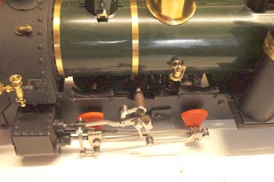 A Simple Steam TestAh
- but nothing is ever simple! I have been feeling a bit guilty about
the lack of progress, but yesterday afternoon, rather than start on the
cab, I thought I would give jack a quick steam test. It would be a quick
way to confirm my timing was right and that the Slomo was working
smoothly and easier than starting the platework. Or so I thought.....
I
replaced the boiler which, to be honest, is a bit of a pain because it
is such a tight fit in the smokebox. I did ease the hole with a sanding
drum on the Dremel when I first fitted it (end removed excess silver
solder from the outside of the boiler with a fine file), but it is still
tight. Then I had my little ritual trying to re-fit the pipe unions.
Somehow I get one end on and the other will not fit, so I loosen the
first and try again - and again - taking great care not to cross thread
the unions. Such fun! Finally it was all connected and tight, so I oiled
round, filled the boiler, lubricator and gas tank, and lit up with the
engine on blocks. At this point I checked to see that it would go
into gear - and found it would only go into reverse as the weigh shaft
fouled the Slomo. "Bother" I thought. Oh well, I would just try it in
reverse. It raised steam and started just fine - very smooth - but the
timing beat, which is very audible with the Chuffer, was not quite
right. At this point I decided that I must adjust the weight shaft so
that the lifting arms would allow me to select forward. Oh joy - the
grub screw on the left hand lifting arm (which would normally be on the
right) was now facing down and unreachable! I will gloss over the
next half hour, but suffice to say that I did manage it, after a
fashion, with only minor burns. And there is just enough movement space
between the Slomo and the boiler for the weigh shaft to allow both gears
to be selected. More steam and I could hear (as could the neighbours!)
that the timing was slightly out in forward as well. So it is back to
the proper work bench to remove the smokebox so that I can access the
cylinders for re-timing.
The moral of all this is, of course,
check and re-check that everything is working and adjusted before
lighting up. Mine had been fine on air and the weigh shaft had been fine
before the Slomo. The thing is that the boiler is set very low on the
loco which makes the adjustment crucial when a Slomo is fitted. Brian
reports that he has also found it tight, and a solution to the
adjustment of the left hand lifting arm is to drill, tap and fit a grub
screw on the top. We shall see........
A Matter of TimingOh what fun I had yesterday! A simple job and no pressure - time to myself in the workshop. Only it didn't turn out to be quite so simple........ Firstly the weigh shaft/lifting arm adjustment. Try as I might, I just could not get the grub screw in the left hand lifting arm tight enough. The small Allen key has to go in from below and at a slight angle I could not give it enough welly (torque!). I had to remove it to put a new grub screw in and that had me perplexed for a minute or two until I realised that I had to release the eccentric rod (that's the one that goes back to the return crank) to allow the expansion link to swivel out of the way. I checked the grub screw and found it to be 3mm thread - but I do not have a 3mm tap, so out cam e the parts box to search for a 6BA one. Luckily I had one, so I set the lifting arm uo to drill straight through the existing hole with a 2.3mm drill. It was then easy to tap it 6BA and the job was done. The grub screw is now on the top and easy to adjust. With the lifting arms adjusted so that I had good travel for forward and reverse, I moved on to the timing. Now here there is an issue, because the smokebox sides overlap the cylinders, making the inner screws in the covers inaccessible. Easy, I thought - just remove the smokebox. So I undid the two screws from below the footplate and realised that the smokebox would not slide forward because of the water filler. Luckily I had not fixed this - it was just a firm press fit. Out it came, but the smokebox is such a tight fit that I couldn't get it off without doing damage or without damaging the paintwork. (Note - make sure that the smokebox is a nice sliding fit on the boiler!!). So I just eased it to one side enough to just access the screws.
When building for the first time one has the instructions at your elbow (or should have), but I knew what I was doing, so just got on with it. After going round in circles a couple of times, I re-read the instructions and it was straightforward-ish. What I didn't notice was that the D nut in the middle of one valve had been lifted and turned - and then through over concentration on reaching the screws, I managed to tighten and lock the whole valve solid. On loosening the cover I found that it was still solid - I had bent the valve rod. Luckily this sounds worse than it is as it was easy to straighten in the vice. I went back to the instructions on assembling the cylinders and they emphasise the need for care - so I can now vouch for that! After that I managed to get it all back together without further mishap and decided to call it a day. I have to say that it was with some trepidation that I fired her up today on the bench. Had all that hassle improved the exhaust beat? Phew - yes it had! Jack's chuff was pretty even in forward and good enough in reverse. With the Slomo she ran very smoothly - though the side play in the drive axle gives a bit of a knocking when on blocks. I will see how it behaves on the track and will consider inserting washers is Jack waddles. I was admiring the slow steady beat when suddenly the sound changed - she was still running smoothly, but something had happened.......... It had indeed - the bolt holding the connecting rod to the piston rod had fallen out! Jack was ticking over on one cylinder and the other piston rod was going in and out on its own. The inertia of the Slomo allowed this smooth and very slow operation and the whole effect was rather surreal :-) The issue of removing the smokebox makes me realise that the idea put forward by Dave Oliver some weeks ago would make this a lot easier. Rather than screwing down through the front footplate with countersunk screws, he suggested drilling clearance holes in the frame spacer and tapping the holes in the footplate. This would mean that the smokebox and footplate could be removed in one piece. I stress that I have not tried this - but it is worth considering.
Side Play
I mentioned the side play above and after a couple more runs on blocks I decided that I had to take action. In the bottom of the parts box were the two Roundhouse steel washers, staring at me, unblinking from their unopened bag. Had I not read the instructions on fitting the fly cranks? Well to be honest, no, as I have fitted wheels so often and have never seen a washer used. My side play was around 1mm (heaven knows why) so clearly I needed to use these washers.
When I tried one, though, I found that it showed: I confess that I did mutter a bit about how a part could be so unsuitable - but then realised that they were, of course, supplied to go with the normal fly cranks: Now there are many ways to reduce the diameter (no filing off the flats doesn't work unless the washer is fixed to the fly crank - don't ask......), but I just filed it undersize so that it does not show at all. I also took a fw thou off the thickness as it was a bit tight. It was pretty snug still when I tightened the screw, but after a few minutes running, all settled down and the thumping had stopped. I have not yet put one on the front axle, but will do when it comes apart next. Fixing the return cranksI suspect some of my readers are wondering when I am going to pin the return cranks - and my plan, at the moment, is that I am not going to. Terry Robinson (Mr Slomo) recommends using 2.5mm high tensile socket head screws which can be made tight enough to hold. I found some on Ebay and just have to wait for them to arrive from China! January 2016
Well the socket head screws and nuts arrived soon after Christmas so it was time to fit them. I had ordered 8mm and 10mm long, just in case, but the 8mm are fine. Whether they really are "High Tensile" only time will tell......! Please note that what follows is not the method recommended by Roundhouse - I am simply reporting on what I have done.
First, here is the screw as supplied by Roundhouse. It is intended as a temporary fix until the return cranks are drilled and pinned with a roll pin.
It really isn't possible to do these up tight enough as the slot head burrs over and they bend. Here is a comparison with the 2.5mm socket head screw:
As the nut is considerably larger, I had to file the flat on the return crank so that it would fit flush and effectivel lock in position. With the screw and nut in position, the nut looked way too big....
....so I filed it to the profile of the casting. And yes, it could be better!
When I refitted the return crank and tightened it up, I found the the 'jaws' of the casting touched and therefore limited the clamping effect. I removed it and put it in the vice so that I coukd run a junior hacksaw down the gap to open it up. In fact I needed to do this twice on one side. Before refitting, I cleaned the oil off both surfaces and it tightened well.
More TimingAll this fiddling about meant that I had to re-adjust the timing and I mentioned further up that the screws are difficult to access without removing the smokebox, or at least moving it a little to one side. Dave Oliver came up with the idea of threading the footplate holes and screwing it from below (for simple(ish) removal and he has since pointed out that he does not drill out the spacer, but uses that thread as well so he only has to turn the screws a couple of turns to release the smokebox. However this does need the water filler to be removable so that the smokebox can be released from the boiler. Brian Wilson has recently had need to re-time his Jack and came up with a neat idea - to make a small right angled screwdriver: This can get at the inner screws to start and then finally tighten them. (Brian Wilson photos)
Following Brian's lead, I made one from a cheap screwdriver by heating the tip to red hot in a blowtorch flame.
I also modifies an old watchmakers' screw driver by rounding the end. This works really well at an angle for running the inner screws in and out with no need to worry about the smokebox. Even More TimingI shall not confess how many times I adjusted the timing before I got it right. I have done it many times before on other RH locos, but not often enough to be an 'expert' and somehow I got fixated with the fact that the return cranks should be at 45 degrees. I also struggled to see the rear exhaust port, and well, we will gloss over the rest! What is a bit scary is that the Roundhouse design is SO tolerant, that they loco ran just fine even when I was way out with my adjustment. It was only the Chuffer (and yes I know I am biased, but this is serious!) that allowed me to hear that it was wrong. The beat should be even 1,2,3,4 not 123-4 or 1234- etc. I do wonder how many return cranks have been pinned with the timing off..........
It is, of course, much easier to set the timing without the smokebox on, but then you don't get the chuff beat. Simply pace a piece of 1/2" tube over the Chuffer and it will be fne.
OK - so to get it right - just follow the Roundhouse instructions! Use a high powered torch to see that rear port cracking open with the crank and piston fully back and do not be afraid to move the return crank until it is right. Then go back and check, and again! I needed to make a number of adjustments to both the return crank and the valve spindle adjustment before I got it right. In fact I found it impossible to get perfect timing forward and reverse, and so opted for spot on forward and a slight compromise in reverse. Brian does the same, so I feel that I am in good company. The nice thing about having decided not to pin the return cranks, is that I can always go back and do it again if necessary. Here is a short video that lets you hear the exhaust beats from my various attempts. I was just filmed on my phone so is not great art! Running InThe good thing about all this adjusting and testing is that the loco has had plenty of running in. So far it has probably done about four hours - so about half way there....... Tightening upWhile I have been fiddling with the timing and running the loco in, various stuff has come loose, so it is worthwhile going round to check tightness. Both my cylinders worked loose. Heaven knows how as I know I tightened them. Honestly....! The weigh shaft ended up with some side play and the star washers on the expansion link pivots needed an extra tap. The fibre washers between the regulator body and the boiler fitting began to leak steam. I tightened the body and adjusted the pipework, but then they leaked again. I added an extra, thin washer and adjusted the pipes again. And I have just noticed that the Slomo chain is a bit slack so that needs adjustment next.......
The Cab - front
Those who are following this account will know that I am trying to keep pace with Brian's articles in Garden Rail Magazine and it is only this month (Jan 16) that he gets to the cab. If I am honest, though, I have been putting it off as some of the things, like the cab edging looked a bit complex and need full concentration - rather than a quick few minutes in the workshop. I mean, that is the way that mistakes happen....... Anyway, it proved to be pretty simple. In addition to cutting from a sheet of brass as shown in Garden Rail, there are etches available from Modelearth Design and laser cut parts from Model Engineers Laser. In fact I have used special etches from Brian himself and I am afraid that these are not commercially available. The only differences are that the main cab is nickel silver and the spectacle holes are modified for special swiveling spectacles which Brian made for me (these are not commercially available either).
The etch for the main part of the cab looked like this: The first thing was to remove the small tags from where it had been cut from the sheet. I snipped them off and filed then smooth. The edges of the etch were also filed smooth and then the whole was cleaned with fine abrasive paper. It is easier to do this first. Now the logical next step would be to bend the sides round, but I wanted it flat so that I could solder the cab edging on easily. Brian recommends 4mm wide by 0.9mm thick brass, bent to shape and held with tape to solder with a good iron. I use a micro torch and so tape was not really an option. I had 2.8mm by 0.9mm strip in stock and so used that - and it looks fine to me. Looking at the drawing, I realised that the hole for the handrail had to be in exactly the right place and really should be drilled before soldering the edge in place. I pladed the cab in position on the footplate and estimated where the front corner shold be - flush with the front of the footplate. I then measured from the back of the etch to the centre of the handrail hole in the footplate and found it was 5.4mm (please check yours - it might be different. Next I made the decision that the edging at the top of the cut out would be level with the vertical cab edge below. I placed a ruler against this and marked the top to show where the edging must end. Then I prepared the edging. I wanted it to have rounded corners and so decided to solder it to another strip of brass so that I could hold it in the vice for filing (and yes I know I could have filed it after soldering!). This was not pretty, but it did the job - and more important, it tinned the side that would be soldered.
I had thought that I would file it to half round, but lost the will after a few minutes so it just has rounded edges on the top.
I then marked it for the handrail hole and again 5.4mm from that. After drilling a 1.6mm hole I could bend it to shape and cut it to length. This was a slow process and to make this and the soldering easier, I pinned the etch to a flat board with spacers underneath (about 0.9mm thick) so that the edging would be centred. The handrail hole was positioned correctly and the edge ended at the mark at the top. You will see that I soldered from the inside as Brian recommends. I painted flux on and used a micro torch and way too much solder - when I had scraped the excess off it looked OK! I then set up the other side and was about to solder when I spotted that I was about to do it on the outside - so I took it off, turned it round and did it properly! Because the edging is tinned, only a tiny amount of solder is needed. Here is the result after cleaning up.
With both edging strips done, I could bend the cab. I did worry for a moment or two the the edging would prevent me clamping it for bending, but in fact the half etches were so good that I could easily bend it by hand while holding the front flat on a board.
I used a set square to make sure it was at right angles, top and bottom and then decided to run a fillet of solder down the bend. Job done!
After cleaning off the flux, it was time to do the final bend on the top of the cab sides. Now without the benefit of a nice big magazine picture in front of me (it's not out yet), I assumed that these tabs should bend inwards. It was odd, I thought, that the half etch line was on the wrong side, but on other cabs I have built, they always fold inwards - so I did - with the aid of a vice, block of wood and large hammer. THE WRONG WAY!
It was only later in the evening that I happened to look at a small picture on my iPad Mini and spotted that they should bend outwards! Oh bother! It is best to do it right first time as I can confirm that it is not easy to bend them through 180 degrees. Here they are correctly bent (vice, wooden block, drift, hammer and some muttering).
The Cab - top backThe top, back part of the cab involves a number of bends, but is pretty straightforward. Here is the etch: I cleaned up the edges with a fine file and then bent it along the half etch fold lines (with the half etch inside the bend!). The centre part is doubled and I soldered this together - though I couldn't find my small clamps so it is far from perfect. A little filler will sort it. I soft soldered the corner joints too. This now fits neatly into the front part and is held in place by 10BA bolts and nuts. Next I need to make some fixing blocks, the bottom back part of the cab and then the roof........
Fixing BlocksThese are the two blocks which will be tapped to take the 6BA screw to hold the cab in position. I cut a couple of blocks from some 1/8" thick scrap, but they could be angle so long as it is thick enough to take the thread. They need to be wide enough to cover the holes in the footplate when in position, but mine might be a bit too wide - we shall see....!
Positioning is critical so I placed the cab in position on the footplate. I made the front flush with the front of the plate and the sides about 1mm in from the edge. The blocks need to cover the pre-drilled holes and clear the base of the gas tank on the lest hand side (or right if you have kept the left hand reach rod. I soldered them in position: I plan to have my roof fixed in position so that I can mount some of the radio control parts on it, so I shall hold it in place with four bolts. I made some angle brackets for the front two bolts (a bit too big!) and made some reinforcing pieces to beef up the bent in tab for the rear two. I did not drill and tap them at this stage.
Cab - bottom backHere the etch was from Brian, but it is the same as the Modelearth one and in brass: The first job was to clean it up with fine abrasive. I use the foam sanding block with the fine grit. Now for the bends - basically it needs to be folded so that there is a channel top and bottom. I clamped the edge in the jaws of the vice (using amuminium angle as 'soft' jaws) and started both bends, taking them as far as I could by pushing with a block of wood. I then held the centre in the vice and tapped them over with the block of wood and a hammer. It is worth taking time to dress it all into position and then clean up any marks where the hammer has been used direct!
I now needed two sliding doors, each the width of the side panels. I had some brass strip a bit wider and so used this (they still fully open). The 0.8mm brass is much thinner than the channels so they either need to be bent at right angles or have some strip soldered on to make them thick enough. I went for the bend and then filed them to a comfortable fit with rounded edges. There will be a thickness of paint and I do not want them to gouge it. Before going further I wanted to see how it all fitted together and so using some straight wire instead of the posts, I tried it and all seemed to be about right. The RoofOh yes, the roof - a simple job if you have nice new brass and a set of rollers! I chose a slightly more trying approach, but at least it would be easier the second time! Brian had sent me a drawing showing the profile and the finished width of "around 125mm" so I was not really sure of the starting width. The length of 100mm was easy though! (see further down for the correct starting width)
I found an off-cut of 0.8mm brass without a single straight side, so I spent some time marking this out and cutting it to size, allowing generous extra width to ensure that I could get a smooth curve (it is easy to end up with flat ends). As the brass was 'hard' and I don't have a set of rollers, I decided to anneal it and use the rolling pin method (please remember that this is an account of what I did, not a recommendation!). When Liz was out, I put it on the gas stove and played a gas torch on it. I could not get the whole thing to glow red at the same time, but so long as each part gets to red, that will do. The slightly uneven heating made it twist but that didn't matter. I allowed it to cool a little and then dunked it in cold water. I then placed it on a folded towel and smoothly rolled it to achieve a curve. This was incredibly easy and there is really very little curve - in fact it is easy to go too far with the softened brass. It might be possible to get a smooth curve without annealing, but I have not tried. I now had a roof that looked like this: Now the question was how to create the distinctive up turns at each side. I did think of leaving the extra width to assist with this, but now know this is a bad idea as cutting to size after bending would be a major pain. I cut it to the size I thought was right and marked it with lines about 2.5mm in (that is the final distance - not the first I tried!). I then put in in the vice jaws to the line. The heavy aluminium angle was not quite wide enough - but that would be OK I thought. Big mistake - and obvious really - the jaws have to be at least the width of the bend. And the bend is not easy - there is no half etch to assist and I found myself resorting to a block of steel and a hammer. So that made a right mess as the soft brass dented as well as bent! Oh Joy! I then spotted that the machine vice on my pillar drill had wide enough jaws and found that a hardwood block and a heavy hammer would do the necessary. I smoothed out the dents as best I could with solder and a lot of rubbing and tried it for size. Mmmm....it was 128mm wide - was that too wide? I sent a query off to Brian and then decided to 'sleep on it'......... Well clearly my unconscious brain had made a decision, because when I read his response "better too wide than too narrow", I read it as "better narrow it"! I went straight out to the workshop and sliced off one upturn (about 3.5mm) and put a new one in using the machine vice and block of wood method. It took a few minutes, including tidying up the edges. The finished width is now 124.1mm with 3mm upturns. It looks fine to me.
The starting width, found by putting masking tape on the profile and marking the edges before flattening it and measuring, is 125.2mm
Fitting the roofI blame the cold. Winter had arrived in Dorset and my workshop was 6 degrees C. Even after 2 hrs of a fan heater it was only 12 degrees. So marking out the holes for the four roof bolts became a bit of a three act drama. The problem (apart from the cold) was that the cab is not rigid and the overhangs make it more complicated. I decided on 2mm overhang at the front, but went round and round in circles before deciding to just do the front two first and do the back two when the roof was secure. I decided on small head 8BA bolts as my numb fingers could not cope with 10BA! I used a piece of 2x1 held vertically in the vice jaws as my 'anvil' fro centre popping the marked holes and then drilled them to clear 8BA. I eventually managed to mark out the brackets through the holes and then drilled and tapped these 8BA (though I did need to move one of the reinforcing pieces as I had managed to miss it).
With the roof bolted in position I carefully measures where the hole for the safety valve should be and also the hole for a gas filler. I marked them and although the safety valve hole went smoothly, disaster struck when I went to drill out the pilot hole for the gas. My brain disengaged and as I went to the pillar drill, I selected the wrong pilot hole to drill out. Half way through drilling out one of the mounting holes, I realised........ Oh Bother.
I drilled out the correct hole and decided that I could repair the wrong one.
I found a small, brass countersunk screw, cleaned it up and cut the head off. Here it is in position with some flux. I also fluxed yet another dent.... After soldering and rubbing down a couple of times, I got it smooth enough and was able to re-drill it. Cab - front holesI needed to drill a number of holes in the cab front and Brian's notes say "position to suit" the various components.
The whistle - my whistle, supplied by Brian, needs a bracket, though others may choose to fit a casting that has its own bracket. First I made a bracket out of 1mm brass and drilled it for the whistle and the 10BA mounting bolts. I have to admit that I guessed the dimensions and made it to look OK to me. I then drilled the 'operating' lever on the dummy whistle so that I could gauge where the hole for the operating wire or chain should go.
I studied the photos and drawings of jack and decided that the whistle is offset from the centre line of the cab by about 9mm and that the dome of the bell chime is just above the cab roof. That put the flat part of the bracket 22.5 mm down from the top of the cab front. I put the hole for the chain about 3mm down, but that really depends on the whistle. With the bracket in position, I marked and drilled the holed (using the 2x1 in the vice as my support for the cab front. Sand box rod - this depends on the sand box and arm that you use, but on mine I reckoned that it should be 38mm in and about 62mm up from the bottom of the cab. Only time will tell if this is correct...... Blower pipe - I went for 35mm in and 65mm up. Reach Rod - I cut a slot 11mm x 3.75mm, 18mm up from the base and starting 6mm in. This seems to be fine for the modified laser cut reach rod. So here is the front of the cab with all the holes and the whistle bracket in position. Please remember that the holes for the swiveling spectacles are not on the normal, commercially available parts.
The Reach RodAt this stage I dug out the laser cut reach rod (from Model Engineers Laser) and modified it using Brian's method on my website (it is not long enough as supplied). I drilled a 1.6mm hole and then used bent 1.6mm brass rod to extend it. I soldered this in position. I then cleaned this up, smoothed the edges and blackened it using gun 'blue' that I happened to have in stock. I could be painted, of course.
Cab - handrail/postsThere are four of these - two short and two long. Brian suggests that they can be turned from 2.5mm steel or made up from 3/32" brass tube. Please note that there is an error in the Garden Rail Article where this is incorrectly written as 2.5mm or 5/32". I chose the latter method and bought a three packs (that's how it comes now) of 3/32" brass tube, 3/32" copper (for the dummy sand pipes etc) and 1/16" brass rod to reinforce the posts. Short posts - With the cab in position, I measured up from the footplate to the bottom of the cab edging. On mine this was about 55.6mm - somewhat longer than the 52mm shown in the GR drawing - and that's why Brian says to check ( and check again).
I cut the tube with a razor saw and built up the post without double checking it in position. I needed to turn it back about 1mm on the lathe so I would recommend trying it in position before soldering. I needed some 10BA threaded rod and luckily had kept some snipped off bolts used to fix the springs to the chassis. I degreased these in thinners. I needed one for the short post and pushed 1/16" brass rod in to fill the tube. A little flux and a ting amount of solder does the job. However hard I tried, I couldn't get the amount of solder tiny enough and so had some cleaning up to do with a fine file. (you could use superglue - though it would be easy to become permanently attached to the post ;-) I then cut the brass to leave a nib exposed to just go through the cab edge and checked again for fit. The cab must sit down square on the footplate. Long posts - again with the cab in position you need to measure from the footplate up to the roof bracket, but as the post sits on the bottom lug of the back plate, you need to subtract this thickness. I was all set to open out this hole until I realised that Brian's clever design makes the post hold the back plate in position. My posts ended up at 124.2mm but others may be different. It is essential to check and re-check. For this I needed two 10BA threaded parts for each post. The thread should protrude by 4mm (I read this after making the posts above!). So now I had the posts and was able to test fit the cab properly to see where the blocks should be drilled etc. Fitting the CabSo now it was time to fit the cab and posts properly so that I could drill and tap the fixing blocks. The first thing I found was that the back sheet would not go into position with the posts fitted as the holes were just a tad too close together. I drilled them out just a bit larger, but it still wouldn't fit, so I filed the holes slightly oval using a rat's tail file. Even though this is 2mm steel it is quite quick to do and is a better solution, I think, than elongating the holes in the brass tabs. The front posts fitted well (they had been tried enough times!) but I needed to check that they were parallel with the side sheet when the cab front was flush with the front of the footplate. I used a caliper to check top and bottom of the gap and they were fine. Phew. With the rear of the loco overhanging the bench, I was able to align the cab (about 1mm in each side) and mark the blocks - up through the footplate holes with a sharp pencil (or a scriber). I then removed the cab and using my trusty 2x1 vertically in the vice as a support, I could centre pop my mark, drill and tap 6BA. Of course hand drilling is just not accurate enough, at least when I do it, so I spent a pleasant 20 minutes with the rat's tail file, elongating the holes in the footplate until it was correctly positioned. I then fitted the back sheet and posts (after loosening the 6BA screws) and checked to see that they were parallel with the cab front by putting the caliper across. They were way out - around 1.5mm too close at the top. Luckily there was an easy solution - I used my faithful rat's tail file to elongate the holes in the rear cab roof support brackets. I was careful just to elongate and not widen the holes as I didn't want to have to use a washer. Eventually it was OK - so I shortened the 8BA bolts and re-fixed the roof. Back sheet door knobsI stared at a lot of photos but I couldn't really make out the door knobs, so I decided to use a couple that I had made many years ago by turning old plug pins using an electric drill and file. I had briefly used them as handrail knobs, but they were way too big for 16mm and went in the parts drawer. I snipped off the handrail and tidied them up before soldering them into holes - after taking care to ensure that the holes matched and lined up. The tiny stub of handrail that was soldered in popped out - which as a bit of a pain. When it was replaces an re-filed it looked OK (but I should have made new ones!).. Looking at these photos, which were taken in very poor outside light (it's raining again) I can see that I haven't mentioned the dome lubricator.....and yes, I still need to get that extra boiler band! Dome LubricatorThis is a small casting of one of the charming bits of brasswork that adorn Jack. The dome is, of course, the heavy cast Lady Anne dome and it needs to be drilled dead centre for the casting to be fitted. There are doubtless a number of ways to do this, but by far the easiest is on the lathe. I put a strip of masking tape round the dome, mounted it in the chuck and drilled it 2.3mm which was a perfect push/press fit for my casting. If you don't have a lathe, find a friend who has!
Boiler BandThe recommended way of getting the boiler bands is to buy the correct number from Roundhouse in the first place! I somehow didn't get round to it, so I made one from 0.3mm brass sheet. Luckily I have a small, rotary metal cutter so it was not too difficult to cut a flat strip 4mm wide. So that was sorted and it was time to paint...... The Cab - paintingLIz was going away to babysit the grandchildren for a couple of days so I had the ideal opportunity. The only problem was that day one was -5 degrees centigrade so I would need some serious heat in the workshop to be able to spray (it needs to be about 15 C). Then I had a brainwave - the utility room was warm and had a powerful extractor just above where I could set up my cardboard spray booth. Yes!!! (with the benefit of hindsight, I would not recommend this unless the domestic authorities are away for at least 48 hrs - the smell takes that long to clear - and are prepared to dust everything after)
I rubbed down the parts with a medium 3M fleece and scrubbed them in the sink, using an old electric toothbrush to get into the corners. I dried them thoroughly in a warm oven then degreased with cellulose thinners. Here are some of the parts ready for spraying: Using scrap wood as supports, as usual, I sprayed all with one thin coat of etch primer. I protected the threads by mounting the posts in holes and using masking tape.
The roof was then given a couple of coats of ordinary primer as I though it would need a lot of rubbing down to cover blemishes, but as it turned out it didn't need it - my filling with solder had been enough. Then it was on to the cab itself. Now there are lots of ways of doing this, and probably the easiest is to spray the cab in body colour and then brush paint the interior with the cream at the top (and black at the bottom if desired). I chose a more difficult route! I knew that I couldn't spray acrylic car spray over enamel, but I could spray the enamel over acrylic, so the inside had to come first. I roughly masked the interior so that the matt black could be applied. It was not crucial to be accurate with this. I then gave it three good coats of acrylic matt black, allowing it to flash off between coats. It then looked like this:
I then removed the masking tape and it went in the oven for 20 minutes at 100 degrees C. It then looked like this:
Next job was to carefully mask it to give the correct line between the black and the cream. I decided that this line would be level with the underside of the cab edging at the back of the side sheet. When I was happy that there were no cracks or gaps (the spray will find a way through if you are not very careful - I can guarantee it!). At this point I made a mistake. I forgot that it is essential to use a high quality masking tape to get a clean line - I should have used Tamiya tape for the line. I used a Peugeot cream car spray: When I removed the tape (after the third coat had flashed off), I remembered! I decided to press on with the outside of the cab and deal with the paint 'bleed' later.
After baking in the oven and allowing it to cool, I did a major masking job to protect all of the inside. I just left the parts that I wanted to be green.
I set up a spot lamp to give me plenty of light - this really is very important as I need to be able to see (and stop spraying) the moment when the paint 'glosses'. I used the Lidl Metal Protection paint that I used on the boiler. This is quite slow to flash off, but one can re-coat after 5 mins. I gave it four good coats, then left it for a while before removing the masking. This was a pain as the paint was very soft and the masking tape was all stuck together. There was a littl ebleed through round the spectacle holes, but I was able to wipe this off with white spirit as this doesn't affect the car spray. Then it had an hour in the oven at 100 degrees. The following day I masked the line inside the cab with Tamiya masking tape: I sprayed some of the black into a plastic lid and allowed some of the solvent to evaporate so that I could touch in the line with a brush. Meanwhile, the posts were sprayed with the high temperature satin black used for the chassi and the inside of the cab back sheet and soors were sprayed with the matt black acrylic. After baking, these were masked over the black, turned over and sprayed with the green body colour.The roof was sprayed matt black inside and out and then (after baking) the under side edge was masked so that any part of the underside showing outside the cab would be black. The holes were also masked on the outside (should have used Tamiya) and then the centre inside of the roof was sprayed cream. When all was hard and dry, I test assembled it on the loco: Cab spectaclesThe commercially available castings need some tidying up with a very fin, flat file and then with fine abrasive before polishing. The glass is available from cousinsuk.co, but they deal with trade so woth checking with your casting supplier.
Mine were the swiveling spectacles and I will gloss over the happy hour I spent fitting them and their 12BA screws and nuts! I fitted the glass by running a thin line of superglue round with a wooden cocktail stick. If you are using acrylic glazing, don't use normal superglue. PipeworkPart of Jack's character are the exposed pipework, which can be dull or polished copper. As my Jack will be the pride of the line, he will be well polished!
Sand pipes - the sandbox casting should be drilled for 3/32" pipe which is available in packs of three from the K&S stand at the local model shop. The sand pipes need to be carefully bent to a profile that suits you. There seem to be so many versions on old photos and models that it really is a matter of choice. I worked on the basis that they would need to take the sand to the front of the front wheels and for neatness I wanted them to pass in front of the dummy spring. It too quite a few attempts to get a smooth curve with enough 'spring' against the inside of the frame to hold it in position without glue or solder. Blower pipe - I believe that this should be close to 2mm OD, but I didn't have any so decided to use the 3/32 again (I might replace this). As the bends are quite sharp and the copper is hard, I annealed the bend points by heating to red heat and allowing to cool. The trouble was that the 3/32" pipe would not go into the smokebox fitting, so I had to solder in a small brass peg that would. By making the finished pipe just a bit longer than the gap, I was able to spring it into position. It holds fine and wll be easy to replace. Clack valve feed pipe - this was just a small piece of 3/32" copper which is sprung into position between the dummy fitting and the Slomo frame.
Here are the pipes in position
Lubricator pipes - it looks like 2mm wire will be right for the rear steam pipes and 1mm for the drains. I am sourcing some of the 2mm from Ebay and using some electrical earth wire for the latter. But that is for another day (see below). Whistle pipe - I cut the sprue short on the whistle and carefully drilled it 1mm before soldering in a short length of 1mm (nearer 0.9mm) copper electrical wire. I had thought I would need another hole in the cab, but I bent it to reach the bracket and it looks OK to me. Safety Valve ExtensionOn Brian's own model, he replaced the Roundhouse safety valve with a Pop version, but I am happy with the standard one. I just needed to make it vent through the hole in the roof. Now as I have a lathe, I turned a fitting and drilled it 9.4mm for a snug fit on the valve body and at the top I drilled it for the K&S brass tube. It would be possible to fabricate it all with sections of descending size K&S brass, soldered together. If making one on the lathe or fabricating it from tube, do be sure to allow a chamber above the safety valve to allow the steam to vent freely. I have seen what happens if the safety valve is not allowed to vent freely and it is not good!!
On mine the brass tube is a snug push fit as it will need to be modified when I fit the whistle valve.
Photo call Jack is now up to the stage that Brian's prototype was in Garden Rail Issue 250, so it was time for some photos and a steaming. And a little video: Blower Pipe againAs I said above, I had ordered a roll of 2mm OD copper wire from Ebay (it is used for jewellery making apparently): This is about 1.9mm OD in practice and comes off the roll as pretty hard wire. It is, of course, curved so the first job was to try to straighten it. I tried rollin a length between to heavy books and also two table mats (leaning hard on them), but no success, do I annealed the copper by heating to red heat. I put the wire on an insulating concrete block and ran a blowtorch along so that it all went red. It looks pretty horrible after - but it is soft. This time rolling it between heavy books did the job and then it was just a matter of cleaning it up with fine wire wool. I bent it to shape easily using a piece of 8mm OD brass in the vice and bending the curves round this. I think I might invest in a set of proper pipe benders (or make some). So now it looked like this and could be sprung into place. As I mentioned above, my fitting was drilled 2mm but you can decide on the diameter and drill your elbow before fitting it to the smokebox. I think it looks better than the 3/32" tube, but it is marginal. Dummy Lubricator PipingAs I mentioned earlier, my dummy lubricators are a bit larger than the commercially available castings so I decided to use the 1.9mm copper wire for the steam feed piped that exit from the rear of the lubricators. It is a bit on the big side, but I like the result.Possibly 1.6mm would be better for the slightly smaller ones, but it is all a matter of choice.
My problem was that I hadn't drilled them out to take this wire and so needed to loosen the nuts inside the cab far enough for them to swivel round for drilling. It would have been better to do this before fitting them! I drilled the rear t0 1.95mm and the drain to 1mm, taking great care not to break through the fitting. Looking at photos of the real Jack, and also photos of Brian's and Harvey Watkins' models in Garden Rail issue 250, I could see that the steam feed pipes are curved round and down to enter a gland on the back of the steam chest. I pondered about this and though that I could secure an 8BA nut to represent the gland by using a piece of thin brass bent over the edge of the steam chest and secured by the cylinder cover. This was my first attempt (with a 10BA nut): I cut a tiny piece of brass and tinned one end with soft solder. When cool I held it with small pliers on a block of wood and drilled out the nut to 2mm ID. I then fluced the bent wire, inserted it and applied the micro blow torch to solder. It really only needs a tiny bit of solder! My second attempt used even less brass strip and an 8BA nut
In the end, most of the brass strip was filed off as only a very small 'lug' is needed. And in this photo you can just see that I had tinned the other end of the wire.
I was now able to fit it in position and adjust the bends. I removed it to flux inside the drilled hole in the lubricator, and then re-fitted it. I protected the smokebox paint with a brass strip held behind the fitting and then heated the joint with a micro blowtorch. Eventually the solder ran - much too much so I spent the next ten minutes removing the excess solder from the copper! A key consideration is to be able to remove the valve chest cover in the future and now just a slight bend will allow the 'lug' to clear it. I did need to file the rear face of the cylinder cover to clear the nut as I had perhaps made the one in the photo too high up. For the dummy drains I used 0.9mm electrical earth wire from lighting cable. This was bent to shape and again one has to think about dismantling in the future. I tried to leave room for the cylinder covers to come off without having to re-bend these wires. I tinned them and soldered them in as above. Click these images to see them larger.
You can bend the pipes to suit yourself. Some chose to make the steam feed drop diagonally to the fitting, but I chose to drop vertically and then bend inwards.
I rather like the chunky look of the pipework!
Snagging
With the build complete, other than the radio control and whistle, it was time to do the snagging. There were a number of little things that were not up to scratch so I will deal with them here. 1. The first was the buffer beam paint. I have now stripped and resprayed the buffer beams in a gloss acrylic as the matte HT paint just rubbed off. I preferred the matte, but this should be more resiliant. Click on the image to see it larger.
2. The chimney, which I had secured with the high temperature paint had worked loose (so that was a bad idea). I removed it, cleaned the surfaces with thinners and am trying Loctite. We shall see! 3. I thought I had cured the steam leak where the regulator screws on to the boiler turret, but it was back. Because I had ended up with the lubricator slightly above the footplate, it could move down and loosen the joint. I remove the lubricator and pipe assembly and re-annealed the pipe to the regulator. I just heated it with a small blowtorch, paint on, to red heat. The paint came off that bit of pipe, but that was easily touched up. I thoroughly tightened the regulator and re-bent the pipes to give a better fit. It seems to be OK!
4. With the gas valve well forward of Brian's suggested position, it was difficult to reach. I removed the brass knob. drilled it opposite the grub screw and soldered a short piece of brass rod in. I also cures a tiny gas leak from the valve union by cleaning the faces and tightening.
Fitting Radio ControlThere are many ways of fitting radio control to Jack - and there is no right or wrong way (so long as it works!). Brian has mounted his servos etc. in the top of the cab on one that I have seen in photos and he tells me that there will be a future Garden Rail magazine article describing his method. This top mounting has the advantage that everything is easily accessible and indeed, that was what I originally planned to do. However, when I faced it on the bench I changed my mind. Because I film my locos quite a lot, I wanted the cab to be as clear as possible and that meant putting the batteries and receiver below the footplate and the servos low down. There would be three of them as I would be fitting a radio controlled whistle valve and whistle that Brian had made for me (he will also be describing this in a future Garden Rail magazine article). And the whistle itself, which was supposed to go between the frames below the footplate would need to be relocated. I purchased a Saturn 2.4ghz transmitter, which came with a nice small receiver, together with three 9 gram, metal geared micro-servos from my local model shop. I also bought a sliding on-off switch and a 4 x AAA battery box. I decided that I would use Duracell alkaline batteries rather than Nimh and so didn't need a charger socket.
There was another small detail - and that was that I had to be able to easily connect the reach rod to the servo horn on the reverser servo. This has to be done after the cab is fitted and with the manual lever was a real pain!
The plan was for the reverser servo and whistle valve servo to on the right hand side of the cab where the reverser lever had been and the regulator servo to be above the footplate among the pipework, as this was dead space anyway.
Two important thoughts occurred to me at this stage. Firstly I should have ordered a radio control regulator from Roundhouse (not essential but preferable if a Slomo is fitted as it allows wide regulator opening) and secondly I should have drilled a hole or slot in the footplate for the servo plugs to go through (this would have been a lot easier at the chassis stage.
The Brackets
I made the brackets from an offcut of 1.2mm thick brass. It had started life as a brass door plate and this piece had most recently been used to test etch primer and the high temperature paint (and I can report that it was very difficult to remove!).
The first bracket needed was a combined one to take the reverser and the whistle servo. I first bent a piece of brass to shape and made a cut out for the servo. The base is wider than the top as I wanted the servo close to the boiler, but the mounting holes used for the manual lever were some way towards the edge of the footplate. In practice, i found that the thin strip on the left was not strong enough and so soldered in a brass support post. I then found that one mounting hole coincided exactly with the post and so had to drill that to soft solder in a piece of 6BA studding. Lucky eh?!
The bracket was also drilled for the servo mounting screws and for the whistle servo mounting bracket.
The whistle servo bracket was bent up from the same brass: It screws in position with two 6 BA screws. I did consider soldering it, but decided to retain the ability to remove it easily. I added a small reinforcing piece. If using thinner brass it would need significantly more reinforcing, but this seems to be fine. The bracket for the regulator servo was bent up from the same 1.2mm brass. After marking out the servo hole, I drilled four holes - one in each corner - and used a cutting disc to half cut the edge and make a cross cut: The waste was easily removed and the hole filed to shape. I then made a shallow cut with a junior hacksaw where the bend was to go. I added a couple of reinforcing pieces on the outside - these were off-cuts from a laser cut kit, hence the fancy shape. I had the crazy idea that I would fix it to the footplate with the self adhesive 3M rigid interlocking "Velcro" type pads and so didn't drill it for mounting.
Testing the Servos and R/C gearAt this stage I decided to test the new radio gear as I didn't want to assemble it all and then find a fault (more about that later :-( ) I had a spare AA battery box and the servos were easily mounted and plugged in to test. I was also able to modify the reach rod which needed to pass through the hole in the cab front. I decided that a snug fit would be sufficient for fitting this to the servo arm as this could be dropped in after the cab was fitted. I soldered an extension made from a 1.6mm panel pin, bent to shape while red hot, bound on with a bit of copper wire and soldered. All seemed to work OK so the brackets were cleaned, degreased and etch primed. You will see that I cut a slot for the reverser servo wire and plug to pass through. They were then sprayed with the satin black HT paint and baked. Fitted in position the reverser servo looked like this: and the whistle servo looked like this: WiringI really do wish I had though of the wiring earlier as I would have cut a slot under the rear of the boiler for the plugs to pass through easily. As it was, I did have a slot where the footplate had been modified for the gas tank bracket. This was big enough for the plugs to pass through, but only when the gas tank had been removed. I then found that I needed to file the bracket to make room for the wires. I then spent a merry fifteen minutes trying to get the 2mm nuts on to their screws.... Viewed from underneath the loco, it now looked like this: There was comfortable space for the Saturn receiver and the AAA battery box
Luckily I had a plug with the red and black wires and so I cut the red and soldered it to the switch - bridging the terminals for a better connection.
The wires were then soldered to the correct terminals on the battery box. The switch was held in position by a cover plate over the slot provided in the frame.
The reverser servo (plug marked with an R) went into Channel 1n the whistle (marked with a W) into channel 2 and the regulator into channel 3. Here it is working well.
As I was a bit concerned about the bare battery box connections I sealed them with silicone sealant. The coverBy pure chance I discovered that I had a Roundhouse etch for the cover. This had come with an R/C conversion kit for my Katie, but she already had one.
This bends easily and just needed the front fold up part shortened to allow for the lower footplate on Jack. This was etch primed and painted satin black before securing with 2 6 BA bolts cut short so as not to foul the battery box etc. Mounting the Regulator ServoThe 'Velcro' idea was a bad one as it flexes. Servo tape might have been OK, but I ended up drilling the footplate to clear 8 BA and drilled and tapped the base of the bracket. I shortened the stainless manual regulator arm and drilled it (beware drill wander, this stuff is hard!). The rod has a Z bend at the bottom to secure it to the servo arm. The question now was - would it open the manual regulator far enough? And would it close OK?
A steam test showed that it needed slight adjustment, but closed nicely and gave far more regulator than I could use on the rolling road. Result!
The WhistleAs I mentioned, the whistle valve and whistle were specially made for me by Brian and he will be giving instructions for these in a futere GR article). He does not supply them commercially but others may do so. it does occur to me that a DJB resonator whistle would be about the right size for this loco. The valve 'banjo' screws into the safety valve bush and the safety valve screws in on top. The valve itself screws into the side of this 'banjo' and would normally point backwards when tight, but I skimmed a few thou off on the lathe so that it pointed sideways. I used the last of my Blacken It solution to dull it down.
I couldn't think how to connect it to the servo - but then I found a Biro spring which did the job a treat. It is not pretty (and may be temporary), but is very effective! I needed to tuck the whistle under the footplate outside the frame and so made a right angle fitting with a bent copper tube. The slot must face downwards and ideally have a slight slope so that water clears easily. It is connected to the valve by silicone tube that is a snug fit on the 1/8" copper. I pondered about various ways to fix it, but had lost the will to drill yet more holes and so made a clip to bolt to the servo mounting bracket studs. In this photo I had jammed a nut in to make the slope.
A steam test showed that the whistle worked superbly! At 20 psi it gave a clean whistle and any over-blow (shriek) at higher pressure could be adjusted for with the transmitter trim. I was concerned that the whistle slot was right next to the chassis cut out, which in turn was next to the battery box. I made a cover plate and soldered this to the clip before painting.
When fitting, I decided to try it straight and it works fine.
Final AssemblyWith everything tested and re-tested, I put jack back together, adding all the little nuts that I had left off before and touching up screw and bolt heads with black paint. At least I would not need to take it apart for a good while.......... I decided that the 3/4" pressure gauge was a bit obtrusive so I removed it, masked round the rim and sprayed the back black. it is already lacquered so the paint sticks just fine. Of course I could still replace it with a 1/2" gauge.
Track testJack was a bit slow to get up steam, but then it was cold with a biting wind. With 20 psi he went beautifully - no steam leaks - and the whistle was a joy! The cab is clean and uncluttered - with plenty of room for a small driver (well it is a very small loco!). Servo Failure!Just as I decided that it was too cold for me and that I would take Jack in to stand proudly on the kitchen worktop, the reverser servo failed - at first intermittent and then total seizure. Quick tests show that the receiver is fine, but the new metal geared servo is shot. This means a major dismantle as the gas tank has to come out to release the wiring. Oh joy :-o
Servo ReplacementI really should have planned for this! The use of 2mm screws and nuts to fix the servos is a real pain - captive nuts or tapped holes in the brackets would have been better (I had the 2mm stuff but no 8 BA screws). Suffice to say that it was a right fiddle getting everything apart and replacing the seized solid servo with an old one I had in stock. I had to use a different servo horn and adjust the reach rod etc. etc. I tested it at every stage and it was after I had refitted the gas tank that things went wrong. Nothing - on any of the servos. Bother! I narrowed it down to the new servo causing the receiver to switch off and so deduced that there was a short circuit somewhere. When I got it all apart again I found that when I had tightened up the gas tank (remember the bracket had been modified to allow the wires to go through the existing slot), I had pinched the wire and created the short. So that was in the bin! I now moved the metal geared whistle servo to the reverser and used a nylon geared one for the whistle. You might think it was easier and quicker the second time - it wasn't - though I did take time to modify and round off the part of the gas tank bracket next to the wires. And just as I touched up the last nut again with black paint, I remembered that I had intended to check the gas jet while the cab was off...... Ah well - I am pretty sure that I can get at this easily though the sliding back sheet doors. The lessons from this are pretty obvious: buy the best quality servos and plan your construction for ease of dismantling. Oh yes, and beware of trapped wires! And again!Wonderful steam test with the loco pulling my Slomo wagon. Fantastic chuff, steam plume and whistle :-) The reverser servo lasted 20 minutes again. This time it didn't seize it just stripped something inside and whirred. I had double checked for free movement of the reach rod and there was virtually no resistance with the travel ending just short of the ends of the expansion link. A phone call to Dave Mees of Abbey Bach Loco Works and the problem was solved: NewPower servos are not up to the job. Dave (who fits R?C for Accucraft and others) reported a pretty much 100% failure rate on these servos. He recommended the King Max 13.5g servo which is the same size as the NewPower 9g.
I now I have to wait for the postman so I took a couple more photos to cheer myself up! And again.....My troubles were not over! Dave had explained that the only servos in the size I needed (I didn't fancy making new brackets) were the King Max that he used for whistles, rather than reversers. These have 'metal gears' and so should be up to the job.
They arrived next day and I decided to just fit the one on the reverser. The tedious disassembly and re-assembly went OK and within an hour I had it running on the bench (70 mph gales outside ;-( ). The servo let go after 10 minutes - the high pitched whine indicating that a cog had stripped or something had come adrift inside. Great! Had it got too hot? A quick check found it was 56 degrees C which didn't seem too bad.... but clearly something was very wrong with three servos failing. About servosGetting the right servo is a confusing business. They come in 'weights' but the 9 gram can be the same size as the 12 gram! Now both are pretty small for the reverser, but I wanted to make the installation unobtrusive and I had never had problems with my usual E Max metal geared servos. It was time to investigate. I undid the four screws in one of the failed New Power servos first. Here is what I found: Oh what a surprise - it did have some metal gears, though these are not much use when the main drive is nylon and the first idler gear (left) is on a plastic axle that had snapped off.
Next I opened up the King Max. You guessed... There is more metal - but the first pinion and the idler are the same and had snapped off in the same way.
Finally i opened a E Max that I had in stock. In fact I had two in stock - the one with the broken lead and one with a broken mounting lug. I opened one up.... Proper brass gears made for hard work! I decided to put the top from the one on the one with the body of the other and I had one good servo for the next attempt. The lession is that "Metal Gears" may just mean "contains some metal gears". This is probably the reason that the E Max ads on ebay show a detailed photo of the gear train! There will, of course, be other good servos.....
The Problem?
The puzzle was why they had broken. Both claim to have substantial 'pulling power' and I was not giving them too much load. I had centred the servos, made sure there was no binding and been at great pains to ensure that the expansion link was correctly adjusted with the valve rod clear of the end in full gear. (the position of the hole on the servo horn determines this).
To be honest, I am not sure what the problem was - but these may gave contributed: 1. I did all my checking of the valve gear on the side of the loco with the servo with just a glance at the other side (after all, it was running perfectly!). But on further examination I found the the valve linkage on the left hand expansion link was touching the bottom of the slot. Maybe that meant that the servo was straining..... 2. The hole in the servo horn was a snug fit on the rod. Maybe the steeper angle in full forward gear made this tighter and applied resistance. 3. The servo at failure was about 56 degrees, ten degrees hotter than the regulator servo. Maybe too hot? There was no sign of heat damage, but expansion of the plastic may have allowed the superfine gear teeth to disengage. The SolutionsI put the E Max ES08MA servo in, with its proper brass gears train. It was slightly smaller and so did not contact the footplate. It does get hot though - reaching 70 degrees C after 30 minutes, but still working fine. It is close to the boiler and could be further away by a few mm. I will put a heat reflector in between the servo and the boiler. I checked and re-checked the lifting arms and servo horn to ensure the correct movement on both sides. I eased the hole in the servo horn and slightly countersunk the top to make sure it wouldn't bind. The result was that the loco ran on blocks for the best part of half an hour and the servo still worked at the end! I did have another problem during all the testing: the new servo started to have an intermittent fault during installation testing. I traced this to the receiver which was flashing on and off. This turned out to be the Duracell batteries which were down to 1.2 volts (so four Nimh might not be good with the Saturn set). New batteries sorted that. Please note that ultimately I found the 9gm servo was just not strong enough - it needs an 18gm one. See below for more info.
Blocked JetI mentioned that I was concerned about gas flow and wondered if the jet might be blocked. It was easy to remove through the back doors and when I unscrewd the jet from the holder, this is what I found: There was quite severe corrosion - but why? The answer, I believe, is down to the brass black (Blackenit) that I used. When I dunked the jet holder in clean water to remove the chemical, I didn't blow it through with water and some of the chemical just carried on working. Another lesson learned! Radio Control Working!The radio works very well indeed - though when the batteries begin to lose power the servos only work intermittently which can be a bit puzzling. I also discovered (after 90 mins steaming and filming) that the transmitter interferes with the microphones on my camera to give a loud buzzing, so that lot went in the bin! Anyway - today I managed to get a few minutes of film with some nice steam effects from the FX Control. NameplatesAn essential part of any finished loco is a set of name plates. The ones shown above were a spare set kindly supplied by Brian, but I wanted to name this loco after my good lady wife Lizzie.
I contacted Tony Willmore at tony@rhoshelyg.me.uk to ask if MDC Plates could do a special set for me - no problem at all. They are 11mm x 28mm with rounded corners and a sans serif font. They took about five weeks (quoted four weeks) which was fine as they are superb quality and worth waiting for. The cost was £27.25 inc UK shipping. The Sumerlands Busybodies had a bit of a party (as usual click to see a larger image): April Update!Well it is now mid-April 2016 and I have needed to do a few things to Jack (now Lizzie!). The hight temperature paint that I used on the fly cranks was hopeless and rubbed off. I scribed the position of the return cranks (remember they were not drilled and pinned) and removed them easily. I tried repainting them with the spray enamel (Humbrol) that I used on the buffer beams but it would not harden (in my time frame) so I stripped it off. I used the original HT paint, baked to 200 C and then I sealed it on with a couple of good coats of a clear laquer It seems to be OK now. I took the loco up to David Turner's Dingle Leigh Railway and made this little film. Although you cannot see it in the final, edited version, the loco derailed many, many times and by the end of filming, was covered in soil and grit. It is a fact that the fly cranks and the cylinder covers hit the deck first when it derails and so it might be worth thinking about a bar across behind the buffer beam to ground first..... If you watch to the final take, you will see that not only are the piston rod glands leaking steam, but the cylinder end caps are too! I had not checked these and had installed them as supplied by Roundhouse. I checked them today and every screw was loose, as were the gland nuts. Worth checking! June Update - trouble shooting againMy last comment was about steam leaks and with everything tightened up, the loco turned over fine and was ready to go.
I was taking her to Chris Tilley's Barle Valley Railway and decided to check the r/c before I went. The reverser would not work properly with just a bit of juddery movement, so I decided to change the batteries. For some reason these seemd to be hot and the replacements heated up too - but then settled down and all seemed to work OK. The loco ran beautifully and Dave Pinniger (one of the stalwarts of 16mm since the early days) admitted that he was impressed! Now Dave is not a fan of radio control, but I was sure that the combination of r/c, Slomo and FX control would convert him. I handed him the controller, full of confidence that this would be his "road to damascus" moment ....and.....nothing. No reverser and no radio control. Lizzie chuffed round on manual, but the moment was gone...... Here she is in action at the BVR: At this point I went on one of my 'wild goose chases'. I decided that the cheap batteries (JCB) were faulty but that the real problem was that the servo was overheating due to the proximity to the boiler. I pondered on various solutions and Dave Oliver even suggested using plywood brackets to insulate the servo from conducted and radiated heat. I decided, in the end, to fit a thin (1/16") plywood spacer between the bracket and the footplate and to use a foil wrapped square of wood to reduce radiant heat from the boiler - this could be moved or enlarged as required. I have to say it was a right fiddle to get it apart and back together again - it would have been so much easier if the servo brackets had been tapped rather than using M2 nuts and screws! Time for a test - everything worked smoothly on the bench so I steamed up in the Summer sunshine. The servo lasted ten minutes. I used a digital infra red thermometer to check the servos. The reverser and whistle servo were both 60 degrees C. The regulator servo on the footplate was 75 degrees C. As both whistle and regulator servos continued to work perfectly, it was not heat that was the problem. Finally I stopped chasing that goose! I disconnected the reverser and operated the motion to see if anything was binding. The answer was no.....but then when I moved the loco a bit and the LH expansion link was at an angle, it bound up hard. I tried each side independently and traced it to the LH valve rod. I had tightened the LH valve gland just a tad - not enough to cause a problem running, but enough to make it bind when operating the reverser when the expansion ling was tilted. I backed it two flats and the problem was gone. Have I found the problem? I don't know, but everything points to it. My dilemma now is whether to fit yet another micro servo, or should I re-make the brackets to take a bigger, more robust one............ Another new Servo...
I really don't know why the proverbial 'penny' defied gravity for so long. Well it finally 'dropped' - the 9gm servo, even with metal gears was just not man enough to deal with any resistance. When all was loose, it worked fine, but it is just not a long term solution. The trouble is that I am always resistant to re-making things, but I did finally accept it! I ordered an 18gm Emax, metal geared servo from Ebay and found a description that gave the dimensions, allowing me to make a start on the bracket. This time I made it (or should I say beat it) out of 1.5mm hard brass sheet. I could have scored it for the bends and then soldered it, but in the end I just used a significant hammer, a large vice and a metal bar for the final shaping. As it was much tougher than the previous 1.2mm bracket material, it didn't need supports and gave enough thickness for tapped holes rather than using fiddly screws and nuts. Here is the servo: Here is the bracket finished in a stipple finish (OK I painted it in a hurry!) next to the original bracket for comparison. The slight dip at the top of the cut out is where the whistle tube passes between it and the boiler. There is another at the front for the servo wire to pass thwough as the front of the bracket is pretty much flush with the front of the cab. I made sure that the srevo arm pivot was in the same place as the previous one, though as it was higher up, some bending was necessary to make it pass through the existing hole in the front of the cab. The whistle servo bracket needed to be bent back slightly to miss the front of the cab - it is all a bit snug. I had plenty of practice taking the cab on and off through all of this and would strongly recommend a simple check list. At the top, write "Remember to put the sandbox rod through the hole before bolting down the cab"!! When all was tested, finally, with the cab off, everything worked a treat. So I put the cab on and found the whistle lever fouled it. I referred back to this article, and found that I had re-installed it upside down :-/ So off it all came and went on the right way. Luckily the Biro spring link is easy to bend and adjust (and also luckily, can't be seen!). So it is now working again - and hopefully for more than 10 minutes!
The RegulatorWell the servo is just fine, but when I ran the loco with a reasonably heavy train to show some visitors, I was just a bit short of power. The Slomo needs a good shot of steam to get it moving and a couple of times with 20psi there was not enough to start on a gradient. My first thought was that I should really have fitted the r/c regulator from Roundhouse - and to be honest, if I were starting a again with the plan to fit a Slomo, I would. I thought I would try to get a bit more opening first.... When I checked the regulator, I found that for some reason I had drilled the hole for the rod at 16mm from the centre, while Katie's is at 13mm. Also, I found that my set up had lost motion at the end of its travel as the angles were wrong. I re-drilled the regulator arm at 13mm and lengthened the control rod to give better control. It worked fine on test - phew! Here she is with the small FX Control hole open on a warm but cloudy day: The Regulator againWell when I last tested Jack the regulator was OK, but perhaps just not as good as it could be - especially with a good load on, so today I 'borrowed' the Roundhouse R?C regulator from my Katie, which is also Slomo fitted. After a merry time finding the right combination of fibre washers to make it fit with the steam union lined up, I tested it and found the regulator wouldn't let any steam through! this is a normal problem (for me anyway) when setting up the R/C regulator as it uses an O ring which is easy to squash by closing it too much before fitting the regulator arm. With the engine cool, I quickly made the adjustment and all was well. Out on the track, the improvement was huge. Now it is easy to give it an initial blast of steam to get it 'unstuck' and then back off the regulator for an incredibly smooth start.
So I definitely recommend fitting the correct R/C regulator if you are fitting the Slomo!
November Update (2016) - trouble shooting againWell I really did think it was all sorted after the last servo, but when I took the loco to Chris Tilley's wonderful Barle Valley Railway, I got one perfect run and then.....nothing on the reverser. I had todisconnect the servo to put the gear in full forward and then unplegged it. As I was only going forwards, this was fine, and I also ran it like this at Roy Woods. Then, I confess that I just could no face it, so it stayed in its carrying box for over a month. One suggestion that Bill Wilson (an authority on vintage steamers) was that it might be what he called 'mechanical wedging' - the sort of thing that happens when a loose drawer jams. It is just possible that my valve glands (or piston glands?) were too loose and allowed the expansion link to wedge... I really don't know - but when it came apart, I re- sorted everything and tested the reverser movement in every position of the expansion link. All seemed smooth so I fitted a replacement servo - Emax 19 gram again as I knew it would fit. When it was in position, I thought I would test it with a spare receiver and battery outside the loco. The servo was not connected to the reach rod, but the horn was in position. I had not turned the transmitter on and when I plugged the servo into the live receiver, the servo kicked way past its normal travel and snapped the horn against the bracket! So was this what was happening? If, in the heat of a steam up, I turned the receiver on before the transmitter, did that cause the servo to self destruct? I just do not know, but since then I have always made sure the transmitter is powered up before turning on the loco. Oh yes - when I took the broken Emax servo apart, there, lurking beneath all the nice metal gears, was a plastic one....
LIZZIE in action again
After a six month gap in filming, on the 2nd November 2016, I made a little film. The Summerlands Chuffer FX Control was open on the small hole and gave nice steam effects in the low Autumn sunshine.
|