Before stripping the loco I decided to sort the wicks on the burner and give it another test run. Once again it performed reasonably, but it struggled to maintain more than 20psi and there was clearly steam blowing by either the pistons or the valves.
Then it was down to business. Four bolts held the body on (well three really as one was missing). Two on the front footplate and two on the cab floor at the rear. With these removed, together with the lubricator drain plug, the body could be jiggled off.
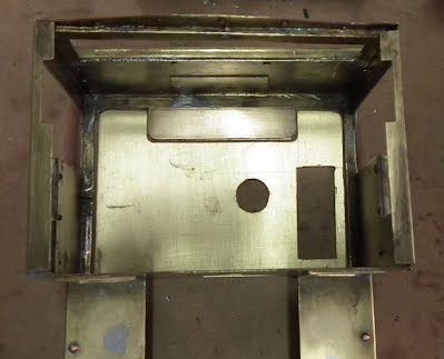
This revealed the very nasty, home-made floor in the cab and the repaired burner shield. it seems that the front corner had rusted away. The body seems quite solid, but has clearly been modified at various times. The handrails on the tank tops are missing and had me puzzled until I spotted the different sized rivets which have been used to fill the knob holes. The coal boxes are very crude and are later additions.
Next the boiler had to come out. It was held by the single boiler band which had a bolt going down through the middle frame spacer. It was in a pretty poor state and had to be completely undone to release the boiler and for the clamp to clear the superheater tube. Getting it back on will be interesting.....
To remove the firebox it was necessary to remove the superheater by undoing the two unions on the front steam pipe. The problem is that even when these are slackened off, the olives on the pipes hold them in place. I had to remove the screw from one end of the front frame spacer snd from the buffer beam bracket. This allowed the frame to be sprung out to release the union. The superheater was removed followed by the firebox. I then removed the footplate floor which will go in the bin!
Now it was a matter of removing the cylinders and valve gear - being sure to photograph it so that I can get it back together.
The cylinders seem to be in good condition, but will clearly need new O rings. There is some wear on the crank pins, but I have yet to find out how they come out of the cranks. Removing the little screw seems to have no effect....... And so I am down to the bare chassis and rather a lot of bits! The wheel bearings are excellent - which is very good news.
When I got to this stage I got distracted into stripping the 'orrible black paint off the body - only to find it was green originally!
Stripping the Body - mysteries revealed
On a recent stripping project (a 1984 Fell engineering Kerr Stuart) I found the modern, dichloromethane free Nitromoors absoluteley useless. For this loco I used Blackfriars "professional" and found it pretty good, provided patience was applied as liberally as the stripper. As I mentioned above, the loco was revealed to be green originally though there was lots of black on top.
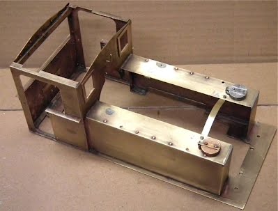
Here we see the loco from above. The crooked cross brace between the tanks is still on as I had not realised it was a bodge. You can see how a larger hole was made for the odd tank filler which seems like a lot of trouble for someone to go to to fit a really nasty bodge. You can also see that the handrail blanking rivets are, on fact, the right size, but appear smaller as they are not soldered in.
The horrible crooked spectacle frames (below) really confused me as the information I have says that Roundhouse switched to etched brass bodies and square windows in 1986. Yet I couldn't believe that Roundhouse could possibly have done something like this. I spoke to Harri at roundhouse this afternoon, but he was still at school when this was made so asked me to send some photos. I went back to stare at it and then decided they had to go!
Now I could see that Roundhouse couldn't possibly have done this, but I was mystified as I just couldn't see what had happened....... Then the penny dropped. I checked my 1983 Lady Anne and found that the spectacle rings are tiny and would fit inside these holes. Then I could see the slight curves on the sides of the right hand one (in the photo) and the mystery was solved. A previous owner has "updated" it to the "square" windows version ....so all I have to do is make some correct round frames and blank off these holes..........
It also fits in better with the date as the loco on Marc Horovitz's site has the round spectacles in 1986.
Looking underneath it is clear that there have been some footplate mods on the front offside, though I cannot work out why. It is clear to see where the cab steps went, though the off centre bracket at the rear is another mystery.
The back of the cab has also received some attention at some stage - the rivets along the top are an addition and one of those centre ones is going to have to move!
So this is where we are at the end of play today. There are a few scraps of paint to remove still, but the handrail holes are revealed and the knobs ordered from Roundhouse. My current plan is to make some plates to take round spectacle frames and then to cut the cab front orifices square to fit them. The brace has been removed and there are some holes to be filled in the tanks. Oh yes - and I have to make a tank filler to match the other one........
Fixing the body
It's a funny thing - but when I went to bed last night, I was convinced that I was going to fit round spectacles, but when I woke up I decided that just sorting out square(ish) ones would be a LOT easier! So my first job today was to make new frames. I decided to learn how to mill them on the vertical slide of my Myford lathe - so it took a long time and produced some mangled brass.......
I eventually got two that I am reasonable happy with and clipped them in position with bulldog clips so I could mark round them. Then I filed the original holes to make them sqaure with the side of the cab etc. The redundant, crooked rivet holes needed to be covered so I decided to solder the frames on and will fill the holes from behind. I will have to mask them when I paint but that will be easier than trying to make them removable.
When these had been soldered on (small blowtorch) I plated under the redundant holes on the tanks and then filled them with solder. This was then scraped and sanded flush.
The final job of the afternoon was to make a tank filler to match the single white metal one. I couldn't find a piece of brass the right size, so I ended up turning it from bronze (not my favourite metal to turn) and then riveting and soldering the brass hinge in place. It is not perfect but will do I think.
Here is the body at the end of play:
Stripping the Cylinders
Well I got a bit distracted by the sunshine today along with shopping and walking along the beach etc., but by popular request, I had a look at one of the cylinders. As predicted by those in the know (Tom and NHN), the valve faces were pretty worn and scored. Definitely worn OUT rather than IN! It is interesting to see that the valve has worn a groove and that the original, 1980's finish was.....well....interesting!
There was plenty of depth in the valve itself so I lapped them on a surface plate using 320, 400 and 1200 grades wet and dry used wet. I need to get some new paper and finish it with 800 then 1200 I reckon, but it looks a lot better
Here is the second cylinder - I was lucky with the studs here too - all came apart smoothly.
Renovating the Valve Gear
Well I amamazed that this worked at all - it just shows how tolerant of wear these locos are! The simple steel rods were all worn with the holes on one con rod nearly worn though. I decided to drill them all out and silver solder brass bearing in. This is the first time I have done this and basically I drilled out 0.14" , turned some brass to push fit (easier said than done!!) and then drilled the new bearing out to 0 .125". With hindsight, I should have made the bearings bigger, but they will do the job for a good many years.
Here you can see a worn con rod with a repaired coupling rod.
And here are the finished rods with just some final tidying to do to ensure they are no thicker than the originals. I didn't bush the valve rods as the wear is only slight.
Luckily the Hackworth "slides" seem to have been designed to be loose and there was no sign of wear. Here they are on the weighyshaft - it takes a lot of punishment as it is inside the firebox.
The crank pins were a complete write off. They are silver steel and threaded 4BA into the cranks. They are further held by small screws which look like they should engage in a cross-drilled hole - but didn't. They were firmly loctited in, but thanks to advice from Tony Willmore, a little heat from a micro gas torch freed them. This is what they look like!
I made new ones from silver steel (again, a lot easier said than done as they are tiny and tended to flex in the lathe). Looking at the photo (mine is the bottom one ;-), I am hoping that the tapered look is an optical illusion - but I may need to do them again!! The Loctite 603 is on order and I plan to file a flat for the small screw rather than cross drill them.
The Chassis
With everything off it, this was just a matter of degreasing and applying the paint stripper. This stuff came off quite well, but there was still lots of mucky wire brushing etc.
Well nearly all the paint is off. I decided not to remove the cranks as this would have meant knocking out the roll pins and truggling with tiny grub screws. You can see here that the frames have been modified (I think) to make it easier to remove the cylinders. The rear buffer beam is heavy gauge to support the meths burner. The front one is a bit bent and is really not strong enough - but that is how it was made and I am trying to retain as much as possible.
Stripping the Boiler
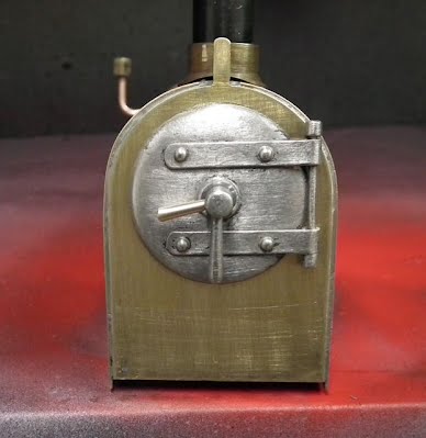
Charles Pooter has a copper boiler with a fabricated smokebox which appears to be silver soldered on. The chimney continues down, through the boiler. The smokebox door is a soft, whitemetal casting, as is the dart. I have no idea how it is held on!
Stripping it was a total pain as it appeared to be stove enamelled. The only reason I started the stripping was because the original finish was clearly chipped under the subsequent layers of paint and it showed. I managed to get much of it off by scraping and useing wet and dry paper. Ugh! Oh yes, and I managed to break off one of the dart handles.
While I was about it, I also stripped the regulator and the lubricator which appeared to have been dipped in thick, black paint. And by then I had had enough.....
The internet is a wonderful thing - Tony Willmore of Rhos Helyg loco Works read my comment about the smokebox wrapper and door and emailed to say that the door is just stuck on and the wrapper is held in place by the Loctited chimney flair. If this is heated to break the joint, and the cap also, then the wrapper comes straight off. Well once I knew the door was stuck on and not bolted, I just looked at it sternly and it fell off! I'm currently not sure whether to repair the dart, make a new one or buy a replacement as I think Roundhouse still do them........
Painting the Chassis
I spent some time today preparing the chassis for paint. I was a bit concerned to find the the stripped and degreased steel was already showing a film of rust - especially the wheels. I treated the previously rusted parts with Jenolite (phosphoric acid) and rubbed it all down with wire wool. I removed the buffer beams and straightened the front one in the vice. There were four tiny holes from a previous coupling so I filled these with copper rivets peened flat and filed smooth (they were a very tight fit).
I set up my usual, cardboard box spray booth and got the fan heater going. Then degreased the chassis again with thinners before priming with Upol Acid etch. This was only realy necessary for the brass angle and bronze cranks, but it works OK on steel too. After flashing this off between coats, I then gave it 30 mins at 80 degrees C in the oven before spraying it all satin black.
After spraying it on its wheels, I inverted it on to two bottle caps as supports. I could then make sure all was given about three or four coats before it had the oven treatment. I did think of masking the wheels, but decided they are best black.
With the chassis sorted, I also found time to paint the weighshaft mounting plates and the cylinder covers.
First task this morning was to spray the buffer beams. I masked behind the beams, so the edges would be red, and wrapped the chassis in cling film. I had thought of leaving a black outline round the beam, but then realised I had not fully sprayed them black (as they were going to be red!). Ah well - I am happy with the result, which had the usual baking.
The Cab Floor
Thanks to David's photos I know that the radio controlled Pooters did not have a floor. The lubricator was mounted low on one side, the meths tank was between the frames and the large servo was the other side - again mounted low. My lubricator had already been raised up so I decided to make a new floor. I used 1.6mm brass which I had cut from an old door plate picked up at a car boot sale a few years ago. It was a bit bent but I cut some flat bits out. I drew round the opening and cut it initially using my "Rage" chop-saw, which showered me with hot brass as usual. Then, after much deliberation, I cut the indent and slot for the reverser servo using a cutting disc in the Aldi version of a Dremell. I finished it with a sharp file and then cut a matching piece for the indent (shown below before soldering) so that the cab mouting plate is symetrical.
The hole for the servo is so large because I have a number of servos in stock that I bought as "Micro" but turned out to be too big. They are smaller than the original Pooter servos would have been, but will look the part I think.
At this stage I made a bracket for the regulator servo and luckily tried a test fit with the boiler and pipework before fitting it. Needless to say I would not have fitted! The pipework will need quite a bit of revision I think - but then it is already much changed from the original. Here you can see the cab footplate with steps added. Luckily I had a set of Swift Sixteen steps that were looking for a home and with some modification to the mount, I think they look great. the Pooter steps were always a bit nasty so this is a justified improvement. I then had to work out how to attach the footplate without getting in the way of the meths tank. I have cut a new frame pacer which will go at the front.
Painting the Body
While I was working on the cab footplate, I put the body in an acid pickle to clean it some more. I use sulphuric acid, but although it cleaned it, the solder bloomed and it will need a full rub down with wire wool again. David Herning emailed to remind me to polish the spectacle frames before painting - so I did. Also Tony Willmore suggested that the tank brace over the boiler is a good thing as the tanks flex so much. I made a brass one and fitted it with small headed 8 BA bolts. It was a right pain as nothing was square! I also knocked out a few more dents on the nearside tank top and filled the resulting ripple, together with the top front tank seams with car body filler. Here is the body at the end of play.
I had the house to myself today, so quite a bit of progress on the footplate and body. First was to fit the cab footplate to the frame spacer and tap this so it could be screwed to the frame. There was much trying in position with the body to make sure everything would fit (don't hold or breath!). When I was satisfied I etch primed it. You can see the detail on those nice Swift Sixteen steps in the "works grey".
Then it was rubbing down the body again and degreasing with thinners. When it was all dry and ready, I gave it a dusting with the Upol Acid 8 etch primer and immediately found some scraps of paint that I had missed in the odd corner. These reacted and lifted off, so not a big problem. Here is the primed body after a quick flatting with used 600 grade wet and dry and another coat.
You can see I just had to mask the spectacles before spraying. Then, while the body was baking, I sprayed the cab footplate satin black, and after a brief spell in the oven, I fitted the footplate.
The body had the satin black treatment next. All was going well until I found some areas inside the tank where the paint just wouldn't dry. There must have been some contamination so I had to wipe it off with thinners and re-prime it. Then the whole thing had a couple more coats before baking. This is how it looked:
I was still not happy, so I flatted it again and gave it a couple more coats! later on I stripped the nice little sprung centre buffers. After rubbing down i etch primed, sprayed them black and then masked the buffer to spray the itting buffer beam red.
And this is how it looked with the buffers fitted and the body balanced on. Oh yes - I had stripped and painted the white metal sand boxes too.......
And inside the cab - the regulator servo is just balanced in position. I am going to have fun fitting the pipework round it!
The Cylinders and Exhausts
I had been rather concerned about the nasty plumbing that came from one cylinder, so I annealed it (red hot in the blowlamp flame) and then fitted the two cylinders in position so that I could ensure some smoother curves up into the chimney flue which rises vertically through the boiler. Of course I couldn't resist trying the Summerlands Chuffer chuffer in position - and it was fine. The label is one left over from the display at Exeter - I didn't print it specially ;-)
Then it was on to rebuild the cylinders using the comprehensive Roundhouse service kit. Note that this has the early cylinders with the rectangular valve chests. The graphited yarn is for the glands on the piston rod.
All went together easily, though I had to be very careful with the tiny 10 BA screws. Later models have 8BA which are bad enough! I had already lapped the valves and surfaces so it was a case of smearing the O ring and gaskets with steam oil and putting it all back together. Here you can see the valve chest - which will need to be re-opened to set the timing.
And here the completed cylinders. It is interesting that on these, the single slide bar really works and the slide (crosshead) is made from brass. This was before the Roundhouse piston glands were made robust enough to not need them. I gather the later white metal crossheads are just decorative.
Painting the Boiler
Tony Willmore had told me that the smokebox wrapper is held on by the epoxied chimney flare, but after giving it as much heat as I felt comfortable with - it just didn't move. I was able to see that there was no room between the smokebox front plate and the boiler, so bolting on a new dart was not an option. One of the handles had gone missing during the stripping, so I turned a new one and drilled a hole in the soft metal using a drill in a pin vice. I epoxied the handle in and then epoxied the smokebox door in place. Time will tell if the glue will withstand the heat!
Then it was a case of rubbing down again with wire wool, running over it with a magnet to remove any strands, degreasing three times with thinners, and etch priming........
During spraying, I had a blob of Bluetac in all the holes, but this was removed before it went in the oven as it goes very sticky in the heat. Then it all got sprayed satin black (Halfords) which I know will take the heat as PPS use it on all their boilers. When this had been baked and cooled, I masked the boiler using tape and a plastic bag. The smokebox was then sprayed matt black (Halfords). I actuall prefer the greyer finish from BBQ paint, but as the stuff I have is a different type of paint (white spirit thinned), I decided to stick with the same type. I am sure the BBQ stuff (Hot Spot) would have been OK ......
And here it is with the cap popped back on. Incidentally this did come off with heat and after cleaning up, I put it back on before the oven treatment. The paint acts as a glue. You can't really see the difference between the matt and the satin here - but it is very different.
And then could I resist balancing it all together to see what it looked like? No! And you will see that I resprayed the nameplates yesterday and re-fitted them with the works plates last night.
I had a bit of a nasty moment this morning, as when I first balanced it all together, I realised that I had not properly checked that the new tank brace allowed it all to sit properly. Luckily I was only out by about 1mm so a little tweaking had it sorted ....phew!
Re-assembling the Motion
Now the keen eyed will have spotted that the cranks are red and the new crank pins are fitted in the photo above. The loctite 603 arrived in the post this morning, but fitting of those newly made pins proved to be something of a challenge.
When I checked the old pins, I was convinced that they were threaded 4BA so that is how I made the new ones. But when I tried to fit them, there was absolutely no chance of getting them in. My first resort was to put the die on them again to make sure I had cut them right. Still no chance. Luckily I had a 4BA tap and with a little gently persuasion it ran through the crank with no problem. Then I realised - the old Loctite that I had heated to free them had hardened in the threads!
I screwed the pins in to the right depth and then marked the end to show where the grub screw went. I then removed them and filed a small flat on the thread. After a thorough clean with thinners, back they went with Loctite and then the tiny grub screw was nipped up.
At this stage I decided the cranks would be red, after seeing the one on the Rhos Helyg site, and so they had three coats of Humbrol.
They are now ready for the rods and cylinders. To be prepared for setting the timing, I downloaded the PDF from the Roundhouse website. I think this will come in very handy - but before that I have to see if it all turns........
First job of the day was to fit the coupling rods. As expected, the new bearings were a bit tight so I sent some time easing them. The easiest thing would have been to use a slightly larger reamer, or even a drill - but could I find one.........! Anyway, I had them turning smoothly after about 20 minutes.
Later in the day I started the main assembly by fitting the connecting rods to the crossheads. I cleaned up the threads and used Loctite here as the head of the screw faces inwards and would be a major pain to re-tighten. Fitting the cylinders was relatively easy - and luckily I remembered to ft the steam pipe. This will have to come off again after testing as it has to go over the firebox, but I need it for the air test.
All the valve gear fitted together reasonably well - it is not exactly robust, but shows little sign of wear. The return cranks fitted and seemed to be tight enough.
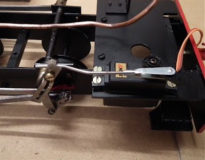
Then I had my first attempt at setting the timing. Basically the valve chest covers had to come off and with the crank at 9.00, both steam holes had to be covered. The valve position can be adjusted by removing the valve rod and turning the spindle so that the valve moves on the screw thread. The problem is that when you turn it, the whole lot wants to move! Anyway, I thought I had it sorted and moved on to fit the reverser servo and make a linkage. The servo end was made from a threaded rod and one of those special clips from the model shop and the lever end was a piece of small hex brass threaded 6 BA and cross drilled for the rod. The hex had once been a post from an old printed circuit board - it really is amazing wgat comes in handy!
Now it was time to put the chassis on blocks to test it with air. I have a large compressor and, after liberally oiling round and down the steam pipe, I put the air gun against the fitting. I confidently expected to see it spin into life - but no. Instead it convulsed and stopped after a quarter of a turn. Mmmm - right, so I adjusted the timing again.
This time it had something of a fit and didn't manage even a quarter of a turn. Not surprising as one of the return cranks had come loose. When I tried to tighten it, I found that it wouldn't, so I took it off and opened up the split part with a cutting disc on the "Dremmel". When re-fitting it, I pinched it closed with pliers to make it easier to tighten.
Now it worked and ran fast in forward gear. There was a fair bit of vibration and the cylinder mounting screws needed tightening. I think the connecting rod bearing might need easing a tad.
The main problem is that it will not run at all in reverse. Back to the timing again tomorrow then - but in the meantime here is the completed chassis.
I woke up this morning realising the obvious - measure the didtance from the valve rod fork to the gland and reset to this after adjusting the valve - easy! Except that try as I might, I couldn't get it set right by using the Roundhouse Carrie method. Maybe there is too much stack in this old system.....so I used a different method. I simply adjusted the valves so that when the wheels were rotated forward, in forward gear, the holes were uncovered an equal amout at each end of the valve travel. It too some trial and error,but when I tried it, it ran beautifully - in both directions! It would even tick over at low pressure (the air gun I was using has a trigger which allows just a little air).
There was some difficulty in finding exactly the right place for reverse gear, and it was when I was considering this that I realised that the clip attachement on the bell crank was causing a proble - both in travel and in the fact that it would foul the body when putting it on. The Mark 2 version, made from brass rod, seems to work OK.
The Plumbing
Happily I discovered that I didn't need to remove the steam pipe to fit the firebox, as by loosening the glands, I could hinge the pipe up so it could slide underneath. While it was hinged up, I took the opportunity to anneal the part of the pipe that is in the cab so that it can be bent to a new shape which will allow the lubricator to be in the cab doorway. It was just a case of heating all but the last half inch up to red heat and letting it cool.
Another job today, which I should have done before, was to de-scale the boiler. I just used kettle de-scaler and hot water, followed by a thorough rinse.
This morning, before I could sort the plumbing, I had to make a new strap to hold the boiler in the firebox. This strap has a single bolt at the bottom which passes through the central frame spacer and the one I removed had had its day. The only brass strip I had was a bit thin, so I doubled the ends and silver soldered them. Then the simple job of drilling two holes went a bit....wrong. Drills will snatch at brass if the edges are not modified, but I confess that I never bother to do this with small drills. The first hole was fine and the drill passed through cleanly into the block of supporting wood. The second one grabbed and coiled the strap round the drill before I could hit the stop button. Doh! I should have known better! So the next job was to unwind what looked like the coil from a corned beef can, and flatten it out in the vice. Here it is with the original - maybe I will get some thicker strip and make another.....
And here it is in position before I used brass black on it:
Once the boiler was fitted in place with the strap, I was able to do the steam pipe plumbing. The shape was quite different from before so I annealed the two pipes on the lubricator by heating them to red heat (not easy with the mass of the lubricator staying cool). I needed to get the lubricator in the doorway and it quickly became apparent that the feed pipe would foul the servo. I had a choice of moving the servo to mount behind the bracket or to let a piece into the pipe - I chose the former.
With the pipes bent and reconnected I was feeling pleased and though I would try the body on - but it wouldn't go over the pipe - so it was re-bent and then it did.
I fitted the pressure gauge and tried the body again - now it wouldn't
go over the gauge! I gently re-bent the gauge pipe while offering up a
small prayer. It was answered - and now it fitted. Phew! I was so relieved that I thought I would open the regulator and put the compressed air gun on the sagety valve hole - just to see it tick over. Up on blocks, I did the deed and nothing happened. Oh bother! What is all the hissing, I wondered. Then I realised - it was coming from where I have forgotten to fit the blow down valve!
So I fitted the valve in the back of the boiler and discovered why there had been no washer when I removed it. With any washer it would end up in the wrong position with the outlet pointing in the wrong direction, unless I was very lucky. Rather than filing a fibre one, I used PTFE tape and it worked. Then it was just anealing the 1/8" copper pipe and making it exit at the rear rather than the front of the loco.
The Burner
This was in a bit of a mess with great blobs of solder all over it. I got the worst of this off (without disassembling the whole thing, and straightened the pipe. I then romoved some of the jagged bits of brass from under the burner tubes with the linisher (bench belt sander). I also made the missing split pin bracket which is shown on David Turner's loco further up the page. The wicks clearly need adjusting here......
The Steam Test
Up to this moment, everything was nice and clean and the unit had run on air like a Swiss watch (ish!). Now things were about to get messy - but I was confident - I mean, why wouldn't it work?
Water in the boiler, meths in the burner and steam oil in the lubricator. The manual regulator handle was fitted for the test and the loco mounted on blocks over the drip tray (yes a rolling road would be better!). Steam was raised, the regulator opened and ........it jerked, locked up and showed me where all the steam leaks were. Not on the pipes (well at least not when I remembered to tighten the steam glands under the smokebox!) but from the cylinder covers and screws. These tiny 10 BA screws were tight, but it still leaks - maybe I should have used silicone rather than steam oil on the gaskets......
After a lot of struggling - I got it to just about run in reverse - but it would not run forward and seemed to hate the process with much hissing and jerking. I convinced myself that the motion must be too tight and was locking up somewhere as it expanded with the heat - and indeed when I got it back to the bench, it seemed to lock up and I found one return crank had slipped.
I systematically took the motion apart and found nothing wrong - except that the one connecting rod was running at a slight angle to the pin. I put it all back together and it all turned smoothly. So back to the blocks and steamed up ....and it ran just fine in forward gear ....and not very well in reverse! But hey - this was progress - until I ran out of water - oops.
I gave it about an hour's running and it has got smoother with a nice tick over. The cylinder covers are still leaking, it is smothered in oil, the boiler paint is a bit sooty (yes, I know, the wicks!) and the vibration is due to some modest wear in the wheel bearings (must get a rolling road). A successful day - but I wouldn't call it relaxing!
Here it is a still of it in action - it was rather loud so at least I could still hear it running while I was in the house:
That evening I ordered a pair of rolling road units from Hog Hill Works!
The Cab Roof
The cab roof, which on a Pooter is a strange, angular piece of tinplate, was in a bit of a mess. The hinge lugs had broken off, the switch bracket had broken off, and the aerial plate had been removed and the hole covered with a riveted brass plate. There were also a couple of spurious rivets.
I made new bracket and hinge plate and soldered them on. I carefully removed a couple of the rivets and soldered a plate underneath before filling the holes with solder. I used rather too much solder on that plate...... I also knocked out a dent and filled it with car body filler.
Then it was etch primed, sprayed matt black and baked in the oven. I let one odd rivet remain to add character!
I fitted a small switch and a battery box for four AAA batteries (stuck on with foam pads). It
would have been better to buy one ready wired, but this is what I had -
and it works. I do need to secure that wire though or those solder
joints will break.
Rather than use screws and nuts for the hinge pivots, I used a piece of steel control rod. This was bent at ight angles at one end and nutted at the other. The nut needs painting!
The Regulator Linkage
The regulator was still in manual form for the steam test, so I needed to make a new arm. I made this from a Meccano boss with a brass plate silver soldered on. This was then shaped on the linisher and drilled with a couple of holes for the control rod. I like the Meccano bosses - a. because I have some, and b. because the hardened grub screw is excellent for the job. I then made a link to the servo after wiring the Giant Cod "RadioLink" receiver up and binding it. I could then see the servo arc and with a bit of trial and error got a reasonable travel on the regulator. In the photo below I have yet to shorten the regulator arm - it lifted the roof when I tried it like this!
I was also able to see the movement on the reverser and am not convinced this is enough. I may have to extend the horn on the servo, though this will create more body fitting problems.......
I will wait for the rolling road to arrive before testing. Also, at present, the receiver is just bundled with the cables in the cab. I need to sort that.
Detail Parts
You may have noticed from the photos that I managed to fit the handrails yesterday. I had debated whether to brass black them, but decided against. The cab knobs are the original plated ones and the tank ones are new Roundhouse brass ones. I also turned a dummy whistle as the original was missing. So here it is at the end of play today:
Testing the Radio Control
Well this bit should have been simple! in fact, from the moment I connected up and switched on the new GiantCod receiver, it began to glitch and twitch. I know - 2.4 ghz can't do that - but it did - and violently! I changed the transmitter - no change. I tried new servos - no change. I tried a receiver from another loco - absolutely fine. I am in discussion with GiantCod, but I bought the receiver for stock about six months ago for stock. We shall see........
I also changed the control arm on the reverser servo to make it longer (an extra hole). It clears the body when fitted and allows the body on and off when fully forward.
The Rolling Road
The rolling road came yesterday from Hog Hill Works - purchased via Ebay. It is a very neat device - well devices really as there is one for each axle.
The loco just stands on them - but it is much better to have them on a solid base as the set up in the photo below allowed some flexing as it was on a tin tray on cardboard.
Steaming and adjustments
With the loco set up as in the photo above, I steamed up and once again demonstrated the steam leaks form the front cylinder covers. The set up was such that there was a fair bit of flexing and vibration.
First I tackled the steam leaks and close examination revealed that one screw, although tight, was standing a few thou proud. It had to come out, and I was just about to undo the buffer beam bolts (and damage their paint) when I realised I could undo the ones on the frame instead. With the beam off, I could unscrew the offending screw to find the thread less than perfect. luckily I have a 10 BA tap and die, so I cleaned up both threads and replaced the screw. I checked all the screws on the other cylinder and found nothing obvious - and it all seems better.
I decided to adjust the timing again - aiming to get the travel equal. You can see the port revealed in the photo below. On the left hand cylinder, I got them both uncovered equally in forward gear (so I thought) but couldn't in reverse - heaven knows why! The right hand cylinder seemed fine so I didn't adjust it.
Back together and steamed up - now it ran perfectly in reverse and barely at all in forward!! I tweaked the left hand timing again - and it ran both ways - though not smoothly......
I then decided to screw the body on and test it outside with the four heavy swift sixteen tankers (a 4 kg load). Here it is ready for action:
And here you can see the temporary arrangement for the receiver in the cab:
Well it went - and much more smoothly than on the rolling road (at least how I had it set up). With enough pressure it ran powerfully with an excellent chuff - I was well pleased - except that it could barely manage a circuit without running out of puff. Back to the bench and I spent ages trying to adjust the wicks. They just wouldn't burn evenly and the front tube would barely burn at all. Luckily, a bag of wick material came with the loco, so I decided to try some stuff that looked like glass fibre. It worked perfectly - and so I replaced all the wicks and decided to try again, even though it was dark outside.
It worked a treat! I perhaps had them set a little high, but Hesperus chuffed round in the dark with his load of tankers and almost had steam to spare. I have to admit that I was well pleased!!! And no I didn't film it - not enough hands and it was pitch dark by the time I finished!
Dumb Buffers
It's funny how simple things like buffers can define the look of a loco - and as David Turner commented, they really are important on a Charles pooter. Jack Wheldon had the chunky wooden buffers on his locos and so did Roundhouse on all of theirs. Once I had decided it was finding the right wood, deciding on the shape and then on how to fix them.
The wood was easy as I had a small piece of red oak left over from my son's lounge floor. This has good colour and a strongly definesd grain. Now Roundhouse had tall buffers with the grain running vertically, and so did Jack on his originals, but they just didn't look right when I tried them. After cutting some out I settled on nearly square (25mm tall by 23mm wide) as - well - they looked right to me! Also I opted to show the end grain as it is more interesting. The buffer beams were clearly not original (unless Roundhouse just glued the blocks on) so I had to bite the bullet and drill them. I just didn't fancy picking up the loco by the buffers and....crash.....so they had to be screwed on.
Here are the blocks after cutting on the chopsaw, linishing on the belt sander and then smoothing with 400 grade wet& dry (used dry). Then they had a few coats of clear lacquer.
I screwed them on with small brass screws after bedding them in a little clear silicone. And here they are:
Daylight Steaming
Yesterday I manged to steam Hesperus in the daylight. We had a reasonable run, though it is clear that I have to adress the valve timing again and have the cylinders apart to stop the leaks. Also, I spoke to Chris Loxley at Roundhouse and discovered the 6 BA motion bolts are a current item and so ordered a couple of packs of six. I may need to fettle the bearings again, but at least I will get rid of some of the slack in the motion. Incidentally, she also told me tha they believe ten hours of steam running are necessary to really get a loko running at its optimum. I have a way to go then!
Anyway, here is a little before and after video:
A Matter of Timing
The motion bolts arrived this morning and this afternoon I had a chance to fit them. I hadn't rally checked when I ordered them, but in fact there are only two to change each side - the one on the return crank and the one on the front of the coupling rod. The ones I removed were worn, but not terminal - you can see them here, with the new one in the middle.
The ones on the piston rod would have meant taking off the cylinders, so I made an executive decision to leave them for the time being. I would have had to modify the bolts for that job as they are cheesehead machine screws. What I did discover when checking the return cranks was that one had slipped a few mm. The slit on this one was virtually closed up by the clamp, so I took it off and opened up the slit with a mini cutting disc (as I had already done on the other one). It seems tight now.
I also repacked the piston glands with a little PTFE tape and then moved on to the timing. To cut quite a long story short, I ended up moving both valves forward by half a turn.
Here it is ready to run:
And run it did - better than ever! I checked it first on air and then steamed up with the body still off. It ran pretty smoothly in both forward and reverse so hopefully there will be a much better exhaust beat out on the track. Of course I realise that it it didn't have a Chuffer fitted, I would have no idea about the timing........ ;-)
Well it ran very sweetly on the track with a nice even beat in forward and not too bad in reverse. I gather from a friend who has a 7 1/4" gauge Romulus with Hackworth valve gear that this is not unusual. It took him three weeks to get his timing nearly right! Here is a little video of it running - I hope you agree it sounds better!
More Detailing
Having removed the coal bunkers, which turned out to be made from a Castrol oil can, the tank tops look a little bare, so I was attracted to club member Tom Beattie's "Locoworks" fire iron set. Luckily Tom spotted that I had ordered the set with the cut away support for the Silver Lady, so today the right set arrived through the post. They are to be screwed on to the tank top with 10 BA screws but for these photos they were just balanced on:
Now I know that I could make some, but I have to say that I couldn't make some like this - as the finish and weathering is just superb. As I said on the daily page, I didn't quite believe they were brass and thought they must be steel and chemically or heat treated. But no, this is an enamel finish which is then dry brushed to give the used look. It is difficult to see in the photo, but rust is even beginning to form on one of them. Nice one Tom!
I borrowed a bucket from another loco and must make a tarpaulin back sheet for the cab........
A Winter Video - 2014
A little video taken at Roy wood's line and starring David Turners Schull and Skibbereen coaches.