by JRinTawa (started 6th May 2012)
Accucraft Leader for the H&MGR This page records my early thoughts and experiences of the "off the shelf" loco then it's evolution into Kaitaki, a generic NZ bush 0-4-2 loco. |
The Leader out of the Box
Accucraft's Leader, and I quote from their description: - ‘Leader’ is based on the 0-4-2ST Kerr Stuart loco based on the Sittingbourne and Kemsley Railway in Kent. The loco is internally gas fired with a centre flue boiler. The model is gauge adjustable from 32mm (‘O’ gauge) to 45mm (‘1′ gauge) and has insulated wheels as standard. The axles run in bronze bearings and all the rods and valve gear are manufactured from stainless steel.The cab roof flips up and over sideways to give access to the gas, water and lubricator fillers. The boiler is fitted with a water level gauge glass and the displacement lubricator has an under floor drain valve. A boiler top up valve is also supplied with the model which will allow for continuous running with the addition of a pump bottle, available from your dealer. Both styles of chimney are provided, straight stack and balloon stack.
Scale is quoted as 16mm to 1 foot (1:19) which makes it somewhat over scale for the approximate 1:24 scale of the H&MGR. (NZ 3'6" on 45mm gauge track) But that will be dealt with later.
So as soon as time permitted it was time to oil the motion and bearings, fill the oiler with steam oil, fill the boiler with 110mm of distilled water and butane gas into the gas tank.
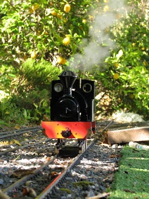
The first run, as the wise heads advise, was on rollers.
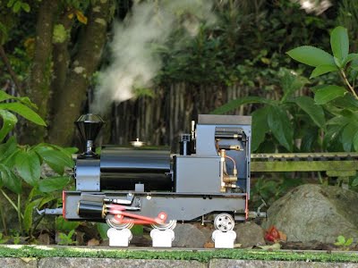
I am pleased to report the first run was a complete success. Being able to light the burner via the open smokebox door is a much more comforting operation than my other live steamer, a Regner Lumber Jack which is lit from the top of the funnel. All be it needing to be rather delicate in not having the gas value to open. Possibly adding an air control ring will improve that, something I'll add in the future. The gas valve did feel a bit lumpy in operation, hard to get it just right, but this was sorted after a run, with the gas tank empty, by fully unscrewing the control and putting a smidgen of Vaseline on the O ring.
The First Runs
Following the run on rollers, and having checked over everything on the workbench after the roller run, the next day was time for track testing. Okay I had run up and down the yard towards the end of the roller run - just to tempting!With the water top up valve fitted I comfortably achieved a 25 to approaching 30 minutes run topping up water every 8 to 10 minutes, later runs proved every 3 loops of our railway is the good timing to top up the water - 3 loops taking the magic 8 minutes.
But as my Leader was still manually controlled at this stage, to keep it under control up and down our 1:50 ruling grade provided much amusement for my wife as she watched. The runs did indicate though that it should be able to be adequately controlled once fitted with radio control, the parts were already on order. As you can see from the video below it was rather to fast at time in the test runs, but it did run, and very well at that. I had read, and heard on videos, how loud Accucraft burners can be. It was very pleasing to find, that with the burner set so Leader held 40 to 50 PSI it was not noisy at all. Perhaps I got a quiet burner? The gas valve does need adjusting as the loco warms and at times during the run. I.e. if the safety's lifting the gas needs turning down.
Leader's First Run
Fitting Radio Control
13th May 2012 Update.
This is my first experiment in fitting Radio Control (RC) to a loco, and after reading lots here, on the old GSM and current GSC forums and studying there photo's I don't have much, if anything new to offer in how the RC is fitted.
Handy pages here on the "Club" are: -
Accucraft Ragleth Edrig r/c for bigjack. Developing Caradoc Bodging a body for Lawley and Edrig Upgrade
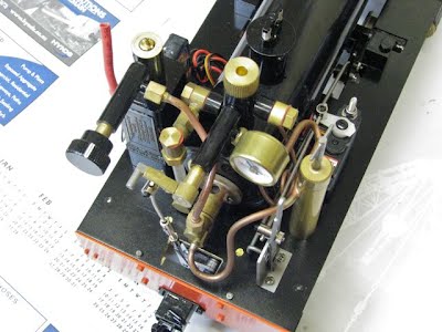
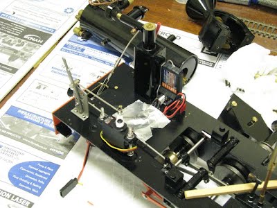
The servo for the reverser fits into the drivers side bunker and the regulator servo is mounted under the floor pretty much following what others have done before me. All parts sourced from Hobby King including the linkage stoppers and the clevis horn. The connection to the regular control arm is a home made bodge from a bit of K&S RHS.
Receiver (RX) and on/off switch are on the fireman's side. RX is stuck with some heavy duty double sided stick foam to the gas tank and the wiring given some token heat protection with foil tape. Batteries are under the floor, currently 4 alkaline AAA's but will get replaced with 5xAAA rechargables when I get to a pack organised. Charging socket which will be used for the rechargables is on a fly lead which tucks in alongside the batteries.
The guidance I was given by all by friends here was perfect - it all worked first time!
And what a joy my Leader is to drive under RC. Once condensate is cleared, working the reverser in reverse then forward etc as done under manual control it's time to depart the yard. Assuming we're driving forward. Reverser into full forward gear, regulator opened up beyond centre then notched back a bit as she moves off out of Kakariki. Opening the regulator a bit more again as the first curve and grade takes affect, then as the curve opens out into a straight, still up grade, notch back the reverser a bit to keep a steady pace.
On up the grade before cutting back the regulator as the grade eases, listening all the time to the throaty exhaust beat thanks to a Summerlands Chuffer. Notching back the reverser a bit more as she comes out of the last curve through the tunnel onto the level through Punga Cliffs. After Punga Cliffs some quick work on both the regulator and reverser around the tight curve before controlling the decent back to Kakariki on the reverser. Control is such that with subtle control I can ease her to a stop on the down grade! And I can shunt too. Finally I can fore fill my dream that has remained with me from boyhood, driving a real steam loco :-)
Modifications to become Kaitaki
8th July 2013 update
The Leader as it comes out of the box is a fine locomotive but as our railway is nominally set as an NZ Bush Tramway with ambitions to become as small branch line some alterations are needed to bring it into scale. To match the normal track gauge of 3'6" I try to scale rolling stock to more or less the correct scale of 1:24 on 45mm gauge track so as it come Leader is a bit bulky. I can do much about the underframe but a new body isn't to onerous a task (I hope). First thoughts were a fully length saddle tank based on an NZR C Class 0-4-2 loco. So a cardboard mock up was tried.
Just for fun a side tank mock up was made, very loosely inspired by an 0-4-2 Barclay that worked on a couple of bush tramways. Both the C and the Barclay were inside framed but lets not let facts get in the way of a good story!
Hence a cunning plan hatched to build two interchangeable bodies and I can effectively have two locos from one!
Side Tank Version
Partly because I think I like the side tank version better, and partly because I'm not sure if I yet have the skills to build the saddle tank, building the side tank version has been started first.
Job one was to fit a wrap of ceramic/thermal blanket supplied by DJB Model Engineering under boiler cladding of 0.05" thick brass sheet. The theory is it should increase the run time as less gas should be needed to raise steam with an insulated boiler, we'll see.
The other reason was to thicken the boiler diameter a bit as it is skinnier than the smokebox as you'll note in the picture below.
Trusting in the hope it is unlikely I'll need to remove the boiler cladding the boiler bands have been soldered in place. Here the last one is temporarily clapped up with wire prior to soldering in place.
Job two, side tanks and cab side. In hindsight I should have put more thought the marking out and included the rear of the cab side cutting out the door way complete, the problem I saw at the time was just how I was going to successfully cut it out. Buy an bandsaw? Score repeatedly with a scrawler till I could flex and snap the cut line? Or score heavily then follow the cuts with a piercing saw? Since I had a piercing saw I gave it a try and working quitely away, sitting at a low level (the work almost at shoulder level) amazingly straight likes were achieved. The piercing saw cutting along the line os least resistance, the scored lines. The other scored lines will be fold lines.
Rivets were pressed while the side were still flat. The area for 4 to 5mm radius front curve was annealed and bent around a piece of dowel. Folding over the tank sides was less succesful on the first side, folding up with just the internal score line. I did attempt to anneal the bend area but the fold was okay but not as sharp as I would have liked. The second side I heavily scored the external side of the fold line and the folding was much sharped and more controlled.
With a band soldered along the tank side both sides were acceptable, though not perfect.
Soldering fine brass strip around the cap opening had me worried for a while, but with nothing ventured nothing gain the first side was
pinned down to a block of Hebel Stone (light weight concrete that pins can be pushed into). A small amount of flux was brushed along the joint before positioning little bits of solder along the joint. Introduce a micro-torch gas flame to melt the solder and it worked!
Picture below is the result following a little clean up work with scrapers and a fibreglass eraser.
Job three, cab front and back. Cutting and riveting of the cab front and back were much more straight forward, curve for the roof scribed using Leader roof as a guide. Cut again with the piercing saw following heavily scored lines.
Sundry length of brass angles were soldered inside to provide structural framing around the cab and joint the rear wall. Positioning these would have been easier if I'd cut the cab side/door from one piece of brass. Again things are pinned to the Hebel Stone block.
Attaching the back section of the cab side and associated beading was a very nervous job I'd worried over doing for several days. The result thankfully was very pleasing having spend quite some time first soldering on the rear cab side then pin jigging up the beading in a similar fashion to the previous work.
Adding Details
25th July 2013 Update.
Starting at the cab end simple hand rails of 1.2mm dia wire bend at right angles at each end (as Chris suggested) and soldered in place with washers soldered in place to represent some form of collar. Brackets for fire irons added to back wall soldered in place plus pins soldered in to represent some form of rivets or bolts. Lamp bracket to be added to, the mounting holes already drilled.
At the smokebox end of the tanks oilers from Locoworks have been added (one each side) along with Leader valve chest cover also from Locoworks. The Leaders original sand boxes have been brought forward to between the sidetanks and the smokebox. Roundhouse clack valves (one each side) soldered onto the boiler cladding. A blower pipe has been made from brass rod and M2 nuts drilled out and then slid over the rod to I hope look like joints.
To try and fill in some of the rather large blank expanse of the Leaders underframe I've added some air tanks from Ozark Miniatures under the cab, bolted with some long bolts made from M2 threaded rod to the running board. The other detail, which is intended to be more a shadow detail than a feature is dummy springs and axle boxes.
The components are 5 thou thick ( 0.005 inch) brass as the backing sheet, dummy axlebox cut from K&S strip 19mmx0.7mm (approx), some 3mm or so angle and Ozark Miniatures loco springs. I had a bit of trouble initially soldering the springs in place, they having proportionally more mass than the rest of the assembly. I have two spare springs so "can I do it" I thought, "can I get just enough heat in and out quick enough with the micro gas torch". I could! Just don't wave the flame over any of the whitemetal of the spring as I discovered. They melt quick then, but luckily it was only a slight melt and I managed to salvage that one. I didn't melt any others - phew!
A small about is filed off the top of the frames so when the 5 thou brass is folded over it's more or less held down by the running board. There are tails of brass below the axle boxes so they can also be folded over once finally painted and in place. I'll possible will put a smudge of silicon in a few spots well clear of the real bearings to ensure the assembly stays in place when finally installed.
There is still some more detailing to go but the work so far has been cleaned up and sits ready for painting.
Painting
23rd September 2013 update
Firstly I give credit to Chris Bird for his excellent tips on painting found here https://sites.google.com/a/gardenrailwayclub.com/club/workshop/painting---the-easy-way Rather than describe in detail how I did it I would rather refer you to the afore mentioned topic. I pretty much followed Chris's advice to the letter, cleaning and decreasing the work scrupulously and practising on some tins first. Hmm okay honesty time, I practise with the spray can etch primer but didn't practise with the top coat. That was a mistake, the top coat cans I had turned out to be the 4" brush version of spray cans. Luckliy I discovered this when doing the small parts first, so after stripping all the paint off with paint stripper and a full reclean the small parts were re etched primed. I then bought some better enamel paint spray cans, from an auto parts chain, and practised more on the tin cans. Success the second time.
Following Chris's example thin coats were applied and "flashed" off between coats using a hair dryer. This is a neat way of working up several thin, very thin coats quickly. I even used the method to work up brush applied finishing coats on some of the small parts.
Here are the dummy spring and axlebox details painted and fitted....
...once the running board is in place they fade into the shadows but give enough detail to reduce the large blankness of the Leader's underframe. The airtanks help with this too (I hope). The smokebox has been painted with high temperature matt black paint.
The body and boiler are painted with satin black, with the green interior brush painted. Don't look to close in the cab, I didn't get anywhere near the quality of the finish with the brush as I did with the spray cans but I did feel it was easier than masking and spraying.
The bold brass ends to the cylinders, and the cylinders overall were brush painted with etch black paint. I'm not sure how well it has coated, time will tell. If I was more confident I would have stripped the cylinders down to paint them, but for now they have been painted in-situ. The red of the headstocks is to be dealt with when the headstock is detailed.
Headstock Detail & New Couplings
While Accucraft chopper couplings work well they are rather bulky for the NZ feel I was trying to capture. I had some Slaters Plastikard "Standard Chopper Couplers" https://slatersplastikard.com/others/16mmParts.php purchased for a wagon building project yet to be started so it made sense to fit them to Kaitaki as Kaitaki would be hauling the said wagons, hmm went I get around to building them.I was a bit unsure exactly how Slaters intended the couplers to be used so I came up with the idea of fabricating a coupler pocket and pivot the coupling on a 1mm dia pin in the coupler pocket, using the supplied spring, for centring. To made the centring work better fitted an M3 washer to either end of the spring. The picture below shows the assembly jig for the coupling pocket. The jig is soldered with high temperature solder, so in theory as long as I heat the coupling pocket up just enough to melt soft solder my jig won't fall apart!
The coupling pocket is bolted onto the new wooden headstock beam(s) with M2 bolts with nuts recessed into headstock. This in turn is bolted onto the end of the underframe. A generous slot is needed to allow for the swing and the washer and nut but it's a pretty chunky bit of brass. I only worked on one end at a time, unbolting the end of the underframe from the running board and each side. The running board keeping everything lined up.
Almost all assembled with running board fitted, 1.2mm dia handrails and Westinghouse valve and glad-hand from Trackside Details http://www.tracksidedetails.com Just awaiting sourcing some suitable chain for the side chains.
You may just spot a vent has been added on to the roof directly above the water top up valve so there is no need now to life the roof to top up the water when in steam, it can be done through the roof vent!
Later with side chains fitted, hooks from Brandbright and a matching Slaters coupling fitted to my one "proper" NZR L wagon I can even hook up the chains. I found hook on the couplings quite tight, but with a slight filing to the back of the hook a snug but workable coupling up is achieved. (So far they have been 100% reliable in service.)
Westinghouse Pump
First up I tried a Gauge 1 pump from Walsall Model Industries http://www.walsallmodelindustries.co.uk but it was a bit small (left photo) so then I sourced one from Roundhouse, it was too big, but Trackside Details (right photo) 1:24 pump was perfect, not surprising as that is the scale I'm attempting base Kaitaki on!
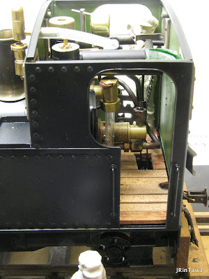
While working in the cab I gave most of the pipe work and fittings either a treatment of chemical blackening or a coat of Humbrol matt or satin black plus an Acme Engineering http://www.acmesteam.co.uk/ ½" dia pressure gauge was fitted. Mike from Acme was very helpful and understanding when I had to return the gauge for one with a different thread. Nothing special you think, but it was, the wrong thread was my fault and I had ordered it 9 months before I got around to fitting it an discovered the mistake. That is good service from Acme Engineering!
The whistle is operated via a length of chain to a Turnigy Micro servo currently stuck with "servo tape" on top of the regulator servo under the floor. I don't trust the servo tape for long term mounting but it will do for now until I can fabricate some form of bracket probably using the same M2 bolts that hold the regulator servo in place. There is only just enough clearance from the rear bogie at 45mm gauge, so I doubt this would work for a 32mm gauge loco.
Window Frames
One of the last jobs was to fabricate wooden windowframes from stripwood, Two overlapping layers glued with PVA glue over a styrene jig. Eight frames to make (inside & outside for each window). I gave them a light wash of indian ink to age them a bit then in a not such wise move I varnished them with some old Humbrol matt varnish, hmm don't use old varnish it can dry with a white powdery finish :-( So they have now been sanded a bit to remove the worst of the white talc.
Clamped for marking to drill for the M1 bolts that sandwiches the frames and the glazing onto the cab front/back.
Front windows fitted. Rear windows fitted.
20th October 2013
Kaitaki has now had a couple of steamings with the side tank body and I am growing increasingly fond of the look.
Almost done (24th Sept), a few refinements to add, (and proof the page for spelling and to read better) but Kaitaki now lives!

