|
by Peter Whatley Train Line 45's DC/DCC Point MotorTrain Line (TL) are a relatively new entrant to the G scale market for track and rolling stock. German made, TL's marketing stresses their "professional" approach to G scale track, with LGB R2 as a minimum point radius and metal frog elements as an alternative to the conventional "dead-frog" type.
TL's point motor has a unique selling point in being fitted with an on-board DCC decoder which can be used in both conventional analogue or DCC modes. The claimed advantages are: inherent flexibility in operation; no need for wiring to a central unit and the granularity of approach (i.e. no need to pay for a central unit with a minimum of 2 or 4 inbuilt decoder addresses). The motor also features additional connectors for both an external light (for an add-on a lantern to indicate point position) and for automated operation via external contacts such as reed switches. The latter facility is the same as that provided for 3 of the 4 connections in a Massoth switch decoder.
This type of combined analogue or DCC point motor from Train Line has replaced separate analogue-only and DCC-only motors previously sold by the company. Do make sure which type you are getting!
Before going further, please note that this is a "servo" type of point motor. Indeed it should be more correctly described as a "switch machine". Instead of a solenoid a miniature motor is used to actuate the tie-bar. In common with all servo devices, this motor is not free to move. Power MUST be applied to change the point's setting. Put another way, you can never:
If either of these features is vital to you (as it may be if children want to move the points by hand) then stop reading now. This is not the device for you.
CAUTION - to avoid damage, before attaching the motor to DCC track it MUST be programmed. Read more in Preparation & Programming.
BasicsAll TL products are made in Germany and the vast majority of their suppliers are there. At the time of writing, only one UK retailer (Glendale Junction http://www.glendalejunction.co.uk/ ) stocks TL products. However, German retailers will readily ship overseas. My example was acquired as part of a large order from a Berlin supplier by a fellow member of G Scale Central. When reviewed, Glendale's price for a single TL DC/DCC point motor was GBP36.90. This can be compared with an LGB or Piko point motor (about GBP22), plus one quarter of a Massoth DCC point decoder (about GBP13.75 per address) or half a Digitrax DS52 (about GBP10). Clearly the Train Line product is slightly more expensive than those, though the cost of wire (and your time/temper installing it!) will level the playing field somewhat. TL's point motor is very much cheaper than buying an LGB/ Piko point motor plus a single LGB/ Piko switch decoder (about GBP43 per decoder, so £65 with the motor).
As supplied, TL provide the point motor, two screws of the standard ISO thread used on all common G scale parts and an instruction leaflet. As might be expected, mine was in the German language only. I assume Glendale may supply a translation for UK users, but if not just read this review for all the necessary information including CV values!
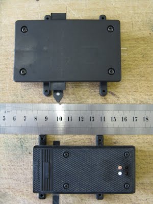
A likely first reaction is surprise at the sheer size of the item. It measures 93mm x 55mm x 20mm high. The picture on the right shows how it compares with the familiar LGB 12010 motor, particular in width.
Note that the two motors have been aligned so that the actuator bars and attachments to the controlled point match up. It's pretty obvious that TL's motor has an extra chunk on the left. We'll have a look at that in a moment.
The TL motor will attach without any issues to LGB or Piko points and any others which share their screw-in attachment points. All six TL screws (4 in the motor's lid, plus the 2 supplied to attach to the point) are coated in what looks like a "Japanned" finish which should resist rusting very well.
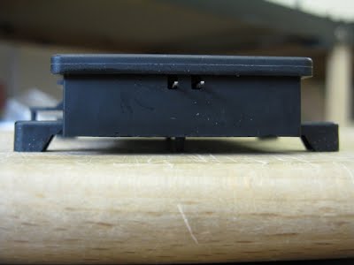
A look from "ground level" shows one of TL's motor's best features: its ground clearance. The whole motor stands 3-4 millimeters clear of its base. This should keep it out of much standing water. Enhancing the feature is a neat drainage hole in the motor's plastic base.
Further weather protection is provided by the motor lid's all-round lip and protruding covers over the actuator bar. All highly desirable!
Not so good are those two protruding connections. Those are the sole means of attaching feed wires to the point motor. There are no screw connections of any sort. The user must find some means of attaching wires to these. We'll come back to this feature later.
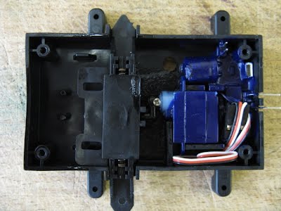
There is no need to remove the motor's lid to get it into service (at least in basic form), but to fail to do so would be no fun at all. So here are the innards exposed! The guts of the motor are an "L" shaped circuit board and a small motor with servo arm attached by a nickel-plated screw. The circuit board is hidden from view except for the large capacitor and two sets of connections by the top right screw hole. Both motor and electronics are liberally covered by waterproofing material. The actuator bar is a very solid item due its potential secondary role as switch for two extra cost add-ons: a point lantern and a micro-switch for point frog polarity (remember TL's own series of points come with metal frog elements). The empty space to the left of the actuator bar is reserved for TL's micro-switch. Two springs provide resilience for "overthrow", ensuring that the servo always travels far enough to make the point blades contact the stock rail.
Top right are two prongs to attach a light (DCC only feature as track voltage is required) and a SUSI socket. Poles 1/2 can be shorted by, for example, a reed switch, to automatically move the point one-way and poles 3/4 to do likewise in the opposite direction. This is a great idea, thoroughly spoiled by use of the absolutely tiny SUSI socket. It is rather hard and pretty expensive to source a standalone SUSI cable in the UK. The only vendor I can find is here: http://www.ekmpowershop2.com/ekmps/shops/aandhmodels/uhlenbrock-31020-intellisound-loading-cable-9172-p.asp at a cost of GBP6.18 per item plus GBP3.50 P&P. TL's own website clearly states that such a cable is available as an accessory, but none is listed! If you have friends using sound decoders who have spare SUSI cables, be nice to them!
Indeed connections are the worst part of the entire motor design. Even if you can find a SUSI cable, the wires will need connecting somehow to an external device which means having a vulnerable connection (SUSI wires are extremely thin...) outside the motor, or very carefully threading cables inside it without fouling the actuator bar. Similarly, if a micro-switch is added, holes will have to be drilled in the motor's base or side for any connecting wires. Really poor design work in my view. Small screw connectors would have been so much better for everything, including the main feeds, but we'll come back to those in Installation.
Preparation & ProgrammingWith "conventional" point motors such as LGB's, preparation is pretty minimal. On analogue layouts, connect two wires to a control box (e.g. a 51750) and off you go. On DCC, the same is true, but with the need to program a switch decoder. For TL's motor, the analogue approach still is valid. The built-in decoder defaults to address zero (0) and is ready to accept analogue commands, though the activating switch must be held down continuously while the servo motor operates (minimum 3 seconds). Why anyone would want to spend GBP36.90 instead of GBP22 for an analogue point motor is a good question. TL claim that it permits users to install their motor on an analogue layout and then upgrade to DCC without changing motor or acquiring switch decoders. This smacks of marketing rather than real world logic to me, but who knows....
In the vast majority of cases I would expect this motor to be used on DCC layouts. Because the decoder is built in, using TL's motor is not a simple "plug and play" option. If attached to a DCC layout without first being programmed, the servo motor will "see" the DCC AC supply directly and jerk uncontrollably in both directions. In addition, damage may be caused to the programming circuitry.
That warning given, programming is simplicity itself. Just connect leads from the motor's two external contacts to each rail of a programming track. Then change CV1 to the required point ID (between 1 and 255). In the illustration you can see me about to input point ID 10. There is, of course, no need to remove the motor's lid! A small click/whirr will confirm that the CV has been changed.
Additionally, you may need to change the "handedness" of the motor via CV40. This is needed as you cannot simply reverse the input wires if the point motor goes left when the right button is pressed on your DCC handset. If that isn't quite clear, just follow this rule: motor attached to the curved leg of a point, CV40 should be set to 1 (factory default setting); motor on the straight leg of a point, CV 40 set to 4. Trust me!
Two other CVs are entirely optional. CV46 adjusts the speed at which the motor works, to provide slow movement of the point blades. I left CV46 at its default setting as even at that, switching the blades takes 3 seconds. Finally, if CV20 is set to 1 all other CVs are protected from (accidental) reprogramming until CV20 is reset to the factory default of 115.
InstallationInstallation also requires a little more thought than usual. Because the actuator arm is not free to move, it may not be possible to attach the motor first to the point's tie bar. If the actuator bar is the wrong way round, do not force it across. Connect the motor to the DCC bus, operate it and only then physically connect to the point. It reads worse than it is....
In DCC mode, the motor will normally be connected to the track (DCC bus). At this point, two design weaknesses of the TL motor become evident. First, the external contacts are at the end furthest from the easiest point of connection: the point's "toe". Fortunately the wires can be teased underneath the motor using the gap between motor and ground level, keeping them as discreet as possible. Mine are then connected to the rails using one Split Jaw rail clamp which has been sawn in half and had 4.3mm ring connectors added to clamp the wires.
The second design weakness is potentially more of an issue. The external connections from TL's motor are bare metal connectors to which wires must either be soldered or mechanically attached through a clamp of some sort or a spade connector. Ideally, any attachment should be as short as possible since any deflection is communicated directly to the point motor's circuit board. Screw terminals within the motor would have been infinitely better!
As the picture shows, I have used individual elements from a strip of UK 3amp connector block on each contact. After testing the whole assembly was smothered in industrial-grade silicone sealant. Not elegant, but it should work. The original 10 year old LGB point motor will be left in situ until I'm satisfied that the new motor is performing satisfactorily. The intent is to reuse it on another point whose motor has failed.
OperationOnce programmed and installed, operation is exactly the same as any other point motor. The TL device can be accessed directly or as part of a "route" of several switches. The obvious difference is that the loud "clunk" of a traditional LGB or Piko solenoid motor is missing. Instead a short whirr can be heard and the point blades move smoothly to their new position. It's rather hypnotic to watch and slightly magical! I can see why Train Line describe this type of motor as being more realistic, though there remains the downside that switching the point casually by hand or by trailing through it are no longer possible. You may have to consider amending your operating habits.....
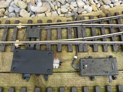
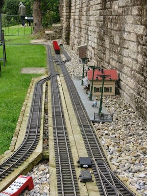
The final picture shows the location of the point used for this new motor on my layout. It is remote from the other points in the station area and was previously "daisy-chained" with another point. It was a cheap and nasty approach forced by running out of slots on my Massoth switch decoders, the nearest of which is hidden in the bird box in the distance. With utter inevitability, I occasionally forgot about this point's setting, running trains into a short dead-end siding. Not good!
The point is used relatively infrequently and there is no need to trail through it. Indeed as a facing point I'd have preferred to have fitted a reed-switch actuated circuit to make sure that trains always took the continuous circuit, not the siding. Due to the TL motor's horrid SUSI interface I've ducked that for the moment.
The alternatives for me were similar to those in the introduction: either another switch decoder and associated wiring at extra expense and time, or - as a backstop - hand operation. This point was a good candidate for the TL motor, BUT it's the only one on my layout that fulfils all these requirements
SummaryThis is an interesting product, but one which I feel is more a "niche" design than something which has widespread appeal. For me, its design faults outweigh the potential benefits from onboard DCC provision and there is little financial advantage in buying the motor. One will be quite enough for my layout. |
Track >

